2 electronic line shaft – Yaskawa A1000 User Manual
Page 12
2 Electronic Line Shaft
12
YASKAWA TM.A1000SW.064 Electronic Line Shaft with Alignment A1000 Custom Software Supplement
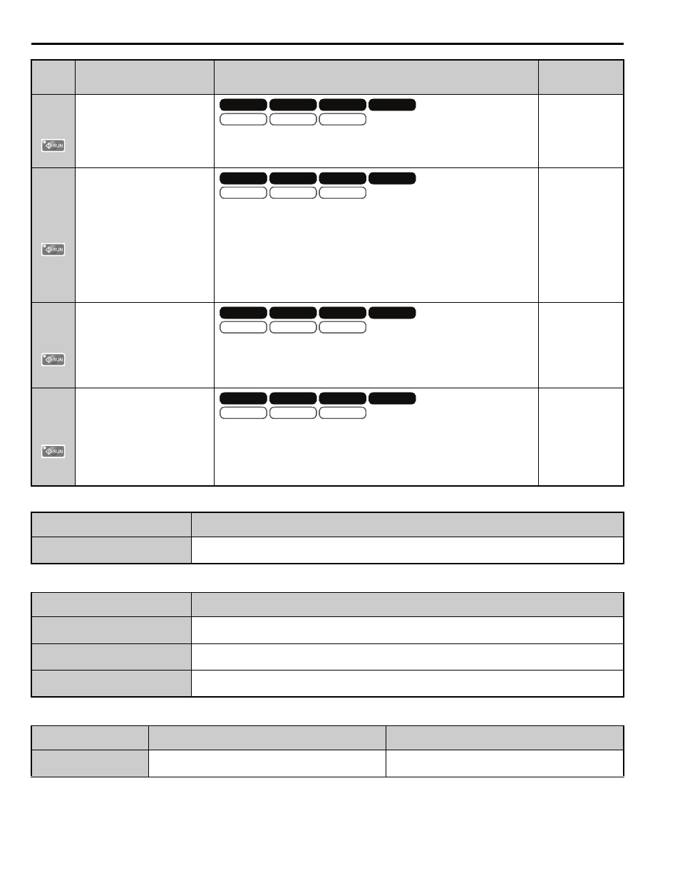
Table 4 Function Group Text
Table 5 Function Text
Table 6 Monitor Group Text
P3-04
(617)
Position PI Limit
(Pos PI Limit)
Sets the limit (+/-) of the position regulator output as a percentage of the
maximum output frequency (E1-04).
Note: ELS modes only.
Default: 8.00%
Min: 0.00
Max.: 10.00
P3-05
(618)
Position Regulator Trim Mode
(Pos Trim Mode)
Selects how the position regulator output is used to trim the follower drive
speed reference (master encoder frequency).
0: Constant. The position regulator output is independent of the master encoder
speed reference.
1: Speed Prop. The position regulator output is proportional to the master
encoder speed reference.
Note: ELS modes only.
Default: 0
Range: 0, 1
P3-06
(619)
Speed Proportional Position Trim
Lower Limit
(SpdProp LowerLim)
Sets the lower limit of the position regulator trim when P3-05 is set to 1.
Set in terms of percentage of follower reference after gear ratio adjustment.
Refer to Function Description on page 16
for examples of how this factors into
calculations.
Default: 10.00%
Min: 0.00
Max.: 100.00
P3-07
(61A)
Ratio Change Speed Agree
Width
(RatioChg SpdAgrF)
Sets the frequency width used to determine “Speed Agree” when the drive is
accelerating or decelerating due to one of the following factors:
Gear ratio change
Change in state of the Follower Disable multi-function input
Change in the state of the Run command.
Default: 0.5 Hz
Min: 0.0
Max.: 20.0
Function Group
Function Group Name
(Digital Operator Display)
P
Coordinated Motor
(Coordinated Motor)
Function No.
Function Name
(Digital Operator Display)
P1
Follower Configuration
(Follower Config)
P2
Follower Motor Tuning
(Follower Tuning)
P3
Position Regulator Tuning
(Pos Reg Tuning)
Monitor Group
Monitor Name
(Digital Operator Display)
Description
U7
Coordinated Motor Monitor Group
(CoordinatedMotor)
Coordinated Motor state indicators
No.
(Addr.
Hex)
Name
(Digital Operator Display)
Description
Values
V/f
OLV/PM
V/f w PG
AOLV/PM
OLV
CLV/PM
CLV
V/f
OLV/PM
V/f w PG
AOLV/PM
OLV
CLV/PM
CLV
OLV/PM
AOLV/PM
CLV/PM
OLV/PM
AOLV/PM
CLV/PM
V/f
OLV/PM
V/f w PG
AOLV/PM
OLV
CLV/PM
CLV
V/f
OLV/PM
V/f w PG
AOLV/PM
OLV
CLV/PM
CLV
OLV/PM
AOLV/PM
CLV/PM
OLV/PM
AOLV/PM
CLV/PM
V/f
OLV/PM
V/f w PG
AOLV/PM
OLV
CLV/PM
CLV
V/f
OLV/PM
V/f w PG
AOLV/PM
OLV
CLV/PM
CLV
OLV/PM
AOLV/PM
CLV/PM
OLV/PM
AOLV/PM
CLV/PM
V/f
OLV/PM
V/f w PG
AOLV/PM
OLV
CLV/PM
CLV
V/f
OLV/PM
V/f w PG
AOLV/PM
OLV
CLV/PM
CLV
OLV/PM
AOLV/PM
CLV/PM
OLV/PM
AOLV/PM
CLV/PM