Troubleshooting, 2 electronic line shaft – Yaskawa A1000 User Manual
Page 15
2 Electronic Line Shaft
YASKAWA TM.A1000SW.064 Electronic Line Shaft with Alignment A1000 Custom Software Supplement
15
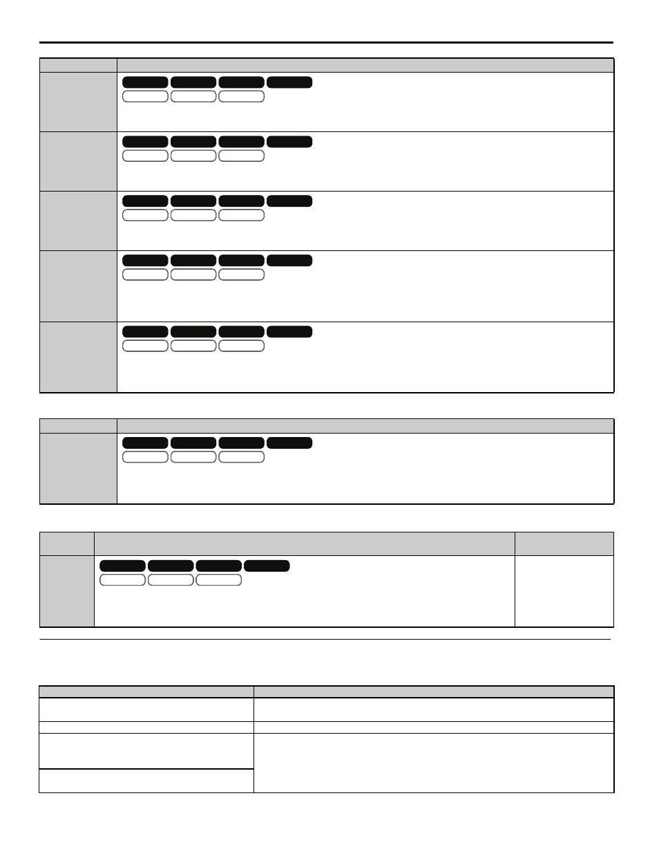
Table 10 Multi-Function Output Settings (H2- )
Table 11 Multi-Function Analog Input Settings (H3-02/H3-06/H3-10)
Troubleshooting
Table 12 Fault Displays, Causes, and Possible Solutions
84
MOP Adjust Increase (MOP Adjust Inc)
Closed: The MOP ratio adjustment is increased. Refer to the descriptions for parameters P2-02 and P2-09 for details.
85
MOP Adjust Decrease (MOP Adjust Dec)
Closed: The MOP ratio adjustment is decreased. Refer to the descriptions for parameters P2-02 and P2-09 for details.
86
MOP Adjust Reset (MOP Adjust Reset)
Closed: The MOP ratio adjustment is reset to zero. Refer to the descriptions for parameters P2-02 and P2-09 for details.
87
Position Error Reset (Pos Err Reset)
Closed: Position error is reset to zero.
Note: ELS modes only.
88
Position Regulator Integral Reset (Pos Reg I Reset)
Closed: Position regulator integral is reset to zero.
Note: ELS modes only.
Setting
Description
40
Follower Position Deviation
Closed: The position error has exceeded the Follower Deviation Level (P2-06).
Note: ELS modes only.
Setting
Description
Analog Output
Scaling
20
Analog Ratio Adjustment
Input value is added to the digital, MOP, and network communication ratio adjustments to form the total
gear ratio adjustment.
Full scale:
100.00%
Digital Operator Display
Description
oPE12
PG Opt Card Err
An additional encoder card is required in the appropriate slot(s) for the selected ELS mode
(P1-01) and follower control mode (A1-02).
Cause
Possible Solution
P1-01 is set to 4 or 5 (ELS modes) and two PG-X3 or
PG-B3 option cards are not installed in the CN5-B
and CN5-C ports.
Install the encoder (PG) option card into the appropriate option card slot(s). Select the
appropriate ELS mode (P1- 01).
P1-01 is set to 1, 2, or 3 and a PG-X3 or PG-B3
option card is not installed in the CN5-B port.
Setting
Description
V/f
OLV/PM
V/f w PG
AOLV/PM
OLV
CLV/PM
CLV
V/f
OLV/PM
V/f w PG
AOLV/PM
OLV
CLV/PM
CLV
OLV/PM
AOLV/PM
CLV/PM
OLV/PM
AOLV/PM
CLV/PM
V/f
OLV/PM
V/f w PG
AOLV/PM
OLV
CLV/PM
CLV
V/f
OLV/PM
V/f w PG
AOLV/PM
OLV
CLV/PM
CLV
OLV/PM
AOLV/PM
CLV/PM
OLV/PM
AOLV/PM
CLV/PM
V/f
OLV/PM
V/f w PG
AOLV/PM
OLV
CLV/PM
CLV
V/f
OLV/PM
V/f w PG
AOLV/PM
OLV
CLV/PM
CLV
OLV/PM
AOLV/PM
CLV/PM
OLV/PM
AOLV/PM
CLV/PM
V/f
OLV/PM
V/f w PG
AOLV/PM
OLV
CLV/PM
CLV
V/f
OLV/PM
V/f w PG
AOLV/PM
OLV
CLV/PM
CLV
OLV/PM
AOLV/PM
CLV/PM
OLV/PM
AOLV/PM
CLV/PM
V/f
OLV/PM
V/f w PG
AOLV/PM
OLV
CLV/PM
CLV
V/f
OLV/PM
V/f w PG
AOLV/PM
OLV
CLV/PM
CLV
OLV/PM
AOLV/PM
CLV/PM
OLV/PM
AOLV/PM
CLV/PM
V/f
OLV/PM
V/f w PG
AOLV/PM
OLV
CLV/PM
CLV
V/f
OLV/PM
V/f w PG
AOLV/PM
OLV
CLV/PM
CLV
OLV/PM
AOLV/PM
CLV/PM
OLV/PM
AOLV/PM
CLV/PM
V/f
OLV/PM
V/f w PG
AOLV/PM
OLV
CLV/PM
CLV
V/f
OLV/PM
V/f w PG
AOLV/PM
OLV
CLV/PM
CLV
OLV/PM
AOLV/PM
CLV/PM
OLV/PM
AOLV/PM
CLV/PM