Yaskawa S12051 for GPD 515/G5 User Manual
Page 10
Flash Software-PID for Trim Control
Option S12051 for GPD 515/G5
Yaskawa Electric America, Inc-www.drives.com
02Y00025-0428 Page 10 of 11
Date: 08/23/01
9. Set the maximum amount of trim the PID can output. Program this value into parameter b5-06 (set as a percentage of
the maximum output frequency E1-04) .
NOTE: for most applications, the integral limit (b5-04) needs to be set equal to or less than the setting of b5-06 to
avoid “wind up” of the PID algorithm.
10. (Optional Step) Test operation of the system prior to running product through the machine.
10a. Be sure the DRIVE light on the digital operator is on. To turn the DRIVE light on, press MENU, then
DATA/ENTER.
10b. Be sure the reference is set to remote by verifying that the REMOTE REF light is illuminated. If it is not
illuminated, press the LOCAL/REMOTE key and/or set b1-01 = 1 (terminals)
10c. Start the machine and the drive, then monitor the output frequency U1-02 while moving the feedback
device. As the feedback device is moved, the output frequency of the drive should increase and decrease
the amount specified in step 9.
11. Run the machine while loaded and adjust the PID parameters to achieve the correct response.
11.a Adjust the gain b5-02. Increase = faster response (too much will result in instability). Decrease = slower
response (not enough will result in poor reaction to step changes or impact loads).
11.b Adjust the PID I time b5-03. Decrease = faster response (too low results in instability).
Increase = slower response (too high and recovery from step changes or impact loads will be slow).
11.c Adjust the PID D time b5-05 only if very rapid changes are expected in the system process. Normally this
setting is left at the factory of zero in order to maintain system stability.
11.d Repeat this procedure at different (expected) line speeds in order to find optimum settings)
Verifying Installed Software Number
For the PID for trim control software option, the software number is 12051. The software version installed in the drive can
be verified by either reading it off of the control board, or calling it up on the digital operator.
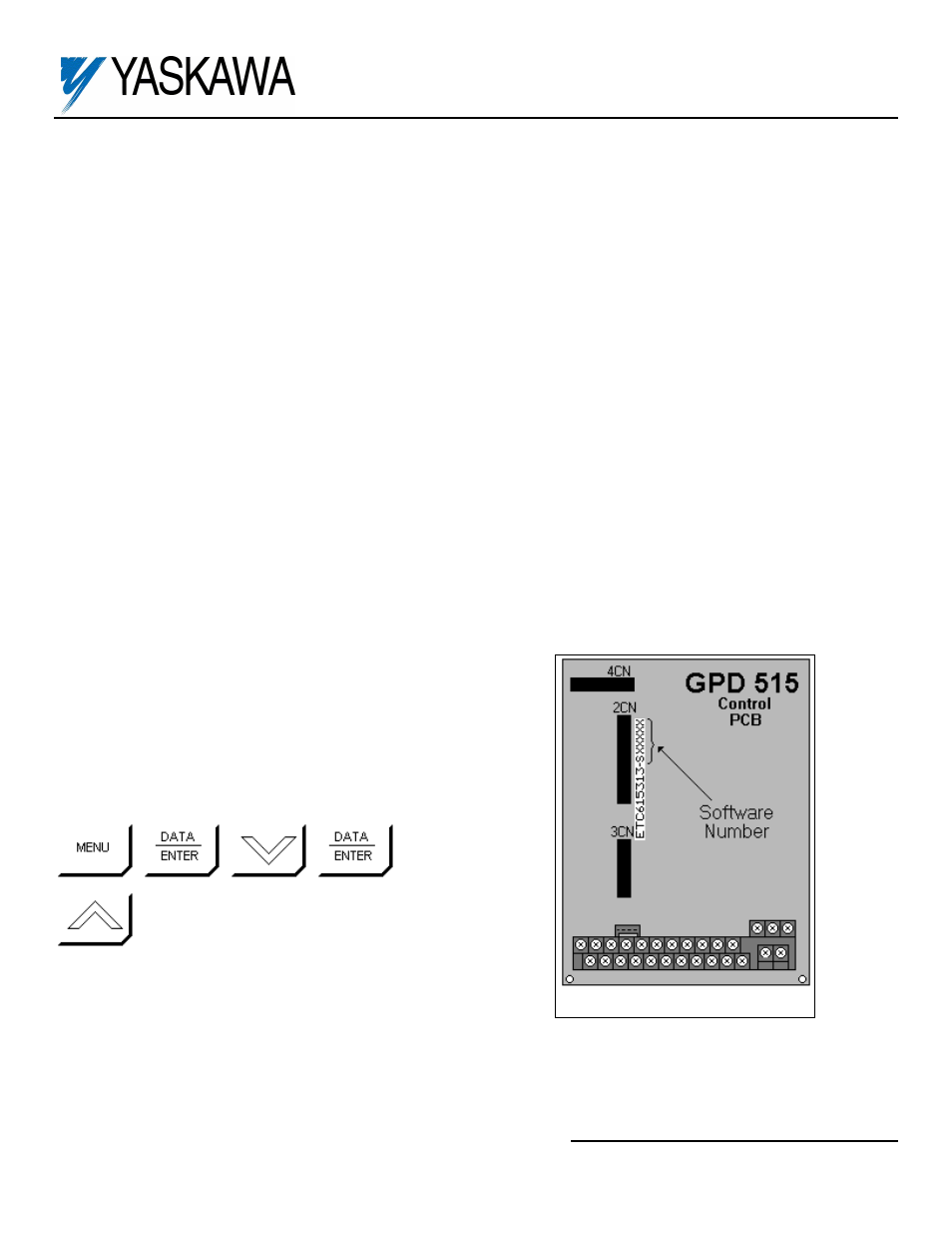
In order to read the software number off of the control board, take the
cover off of the drive and look for the white sticker on the main control
board. This sticker is just to the right of connector 2CN. On it is the
version of the control board, then a dash, then the software number
(see Figure 1). The “S” before the number can be disregarded.
In order to view the software number from the digital operator, bring up
drive parameter U1-14 (FLASH ID). This is done by powering up the
drive and using the following key sequence:
,
,
,
(13 times)
Software Number Location