Yaskawa S12051 for GPD 515/G5 User Manual
Page 8
Flash Software-PID for Trim Control
Option S12051 for GPD 515/G5
Yaskawa Electric America, Inc-www.drives.com
02Y00025-0428 Page 8 of 11
Date: 08/23/01
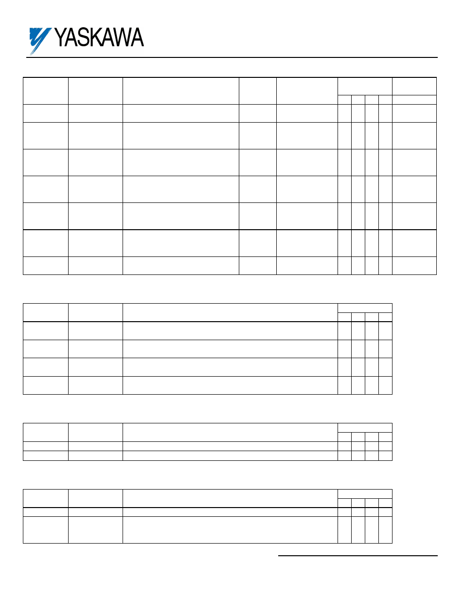
Additions to Table A1-10
(Appendix 1)
(2)
Parameter
Number
Monitor Item Description
Display
Unit
Analog Monitor
Output Level
Access
Level
(3)
Modbus
Address
0 1 2 3
U1-36 Feedback
Monitor
Feedback Level
0.01 V
10V / 10V
feedback signal
A A A
A
0E1H
U1-37
PID Error
Difference between setpoint
and feedback
0.01%
10V / max.
output freq.
(E1-04)
A
A
A
A
0E2H
U1-38
PID Output
Output of the PID control
algorithm before its added into
the main frequency reference
0.01%
10V / max.
output freq.
(E1-04)
A
A
A
A
0E3H
U1-39 Proportional
Value
Output value of just the
proportional portion of the PID
algorithm
0.01%
10V / max.
output freq.
(E1-04)
A
A
A
A
0E4H
U1-40
Integral Value Output value of just the integral
portion of the PID algorithm
0.01%
10V / max.
output freq.
(E1-04)
A
A
A
A
0E5H
U1-41 Derivative
Value
Output value of just the
derivative portion of the PID
algorithm
0.01%
10V / max.
output freq.
(E1-04)
A
A
A
A
0E6H
U1-42
PID Setpoint Actual PID setpoint
(Analog value + b5-07)
0.01V
10V / 10V
setpoint
A A A
A
0E7H
Addition to Table 5-2 Multi-Function Input Terminal Data Settings
(Section 5.32)
(2)
Parameters H1-01 thru H1-06 and terminals 3 thru 8.
Data Function
Description
Availability
0 1 2 3
30 PID
Integral
Reset
Closed = Reset integrator to zero
See Paragraph 5.36F
X X X X
80
Integral Hold
Closed = Hold integrator at its present level
See Paragraph 5.36F
X X X X
81 Positive
Integral Hold
Closed = Will allow integrator level to decrease, but not
increase. See Paragraph 5.36F
X X X X
82 Negative
Integral Hold
Closed = Will allow integrator level to increase, but not
decrease. See Paragraph 5.36F
X X X X
Addition to Table 5-3 Multi-Function Output Terminal Data Settings
(Section 5.33)
(2)
Parameters H2-01 thru H2-03 and terminals 9, 10, 25, 26 & 27 Plus DO-02C option card F5-01 & F5-02.
Data Condition
Signal
Level
Availability
0 1 2 3
40 High
Position
Closed When PID Feedback is above High position b5-10
X X X X
41 Low
Position
Closed When PID Feedback is below Low position b5-11
X X X X
Addition to Section 5.30 Multi-Function Analog Input Terminal Data Settings
(2)
Parameters H3-05 & H3-09 and terminals 16 & 14.
Data Function Description
Availability
0 1 2 3
20
PID Setpoint
Provides a setpoint signal for use with PID control.
X X X X
21 PID
Feed-
back Analog
Input Bias
Mathematically adds to the feedback signal when using PID
control.
X
X
X
X
(2)
GPD515 Technical Manual TM4515