Yaskawa S12051 for GPD 515/G5 User Manual
Page 7
Flash Software-PID for Trim Control
Option S12051 for GPD 515/G5
Yaskawa Electric America, Inc-www.drives.com
02Y00025-0428 Page 7 of 11
Date: 08/23/01
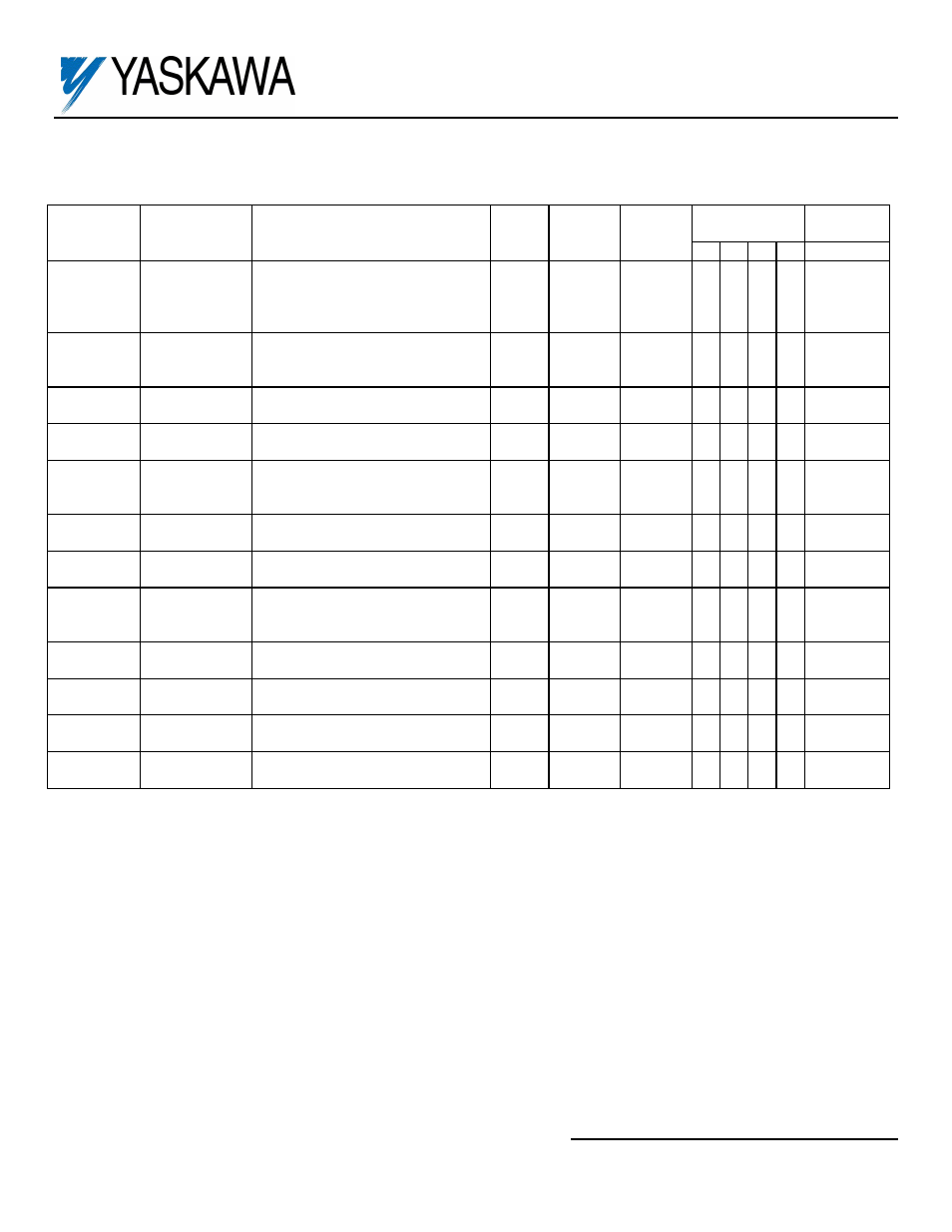
This Table Replaces A Portion Of Table A1-2
(2)
Parameter
Number
Function
Name
Description Incre-
ment
Setting
Range
Factory
Setting
Access
Level
(3)
Modbus
Address
0 1 2 3
b5-01 PID
Control
Mode
Selection
0 : Disabled
1 : PID Output Only
2 : PID + Reference
3 : Accel / Decel Time Change
1
0 - 3
0
A
A
A
A
194H
b5-02 PID
Proportional
Gain
0.01
0.00
-
25.00
1.00
A
A
A
A
195H
b5-03 PID
Integral
Time
0.1
sec
0.0 -
360.0
1.0 A
A
A
A
196H
b5-04 PID
Integral
Limit
0.1%
0.0
-
100.0
100.0 A A A
A
197H
b5-05 PID
Differential
Time
0.01
sec
0.00 -
10.00
0.00
A
A
A
A
198H
b5-06 PID
Output
Limit
0.01
%
0.00 -
100.00
100.00 A A A
A
199H
b5-07 PID
Position
Offset
0.01
V
-10.00 -
10.00
0.00 A
A
A
A
19AH
b5-08 Accel/Decel
Switching
Delay
0.01
sec
0.00 -
10.00
0.00
A
A
A
A
19BH
b5-09 PID
Output
Select
0 : Not Inverted
1 : Inverted
1
0 - 1
0
A A A
A
589H
b5-10 PID
Position
High
0.01
V
-10.00 -
10.00
10.00 A A A
A
587H
b5-11 PID
Position
Low
0.01
V
-10.00 -
10.00
0.00 A
A
A
A
588H
b5-12 PID
Hysteresis
0.01
V
0.00 -
1.00
0.10 A
A
A
A
586H
(2)
GPD515 Technical Manual TM4515
(3)
Capability to view and set specific parameters is dependent upon the Access Level (A1-01) and Control Method (A1-02);
0 = V/f, 1 = V/f w/PG, 2 = Open Loop Vector, 3 = Flux Vector) the drive is programmed for. Each column represents the
Access Level for a given Control Method: 0 = Operation only; Q = Quick-start; B - Basic; A = Advanced; - = not available.