Yaskawa CM061 User Manual
Page 2
Yaskawa Electric America, Inc. –
www.yaskawa.com
IG.G5HHP.12 Page 2 of 9
Date: 11/06/06 Rev: 06-11
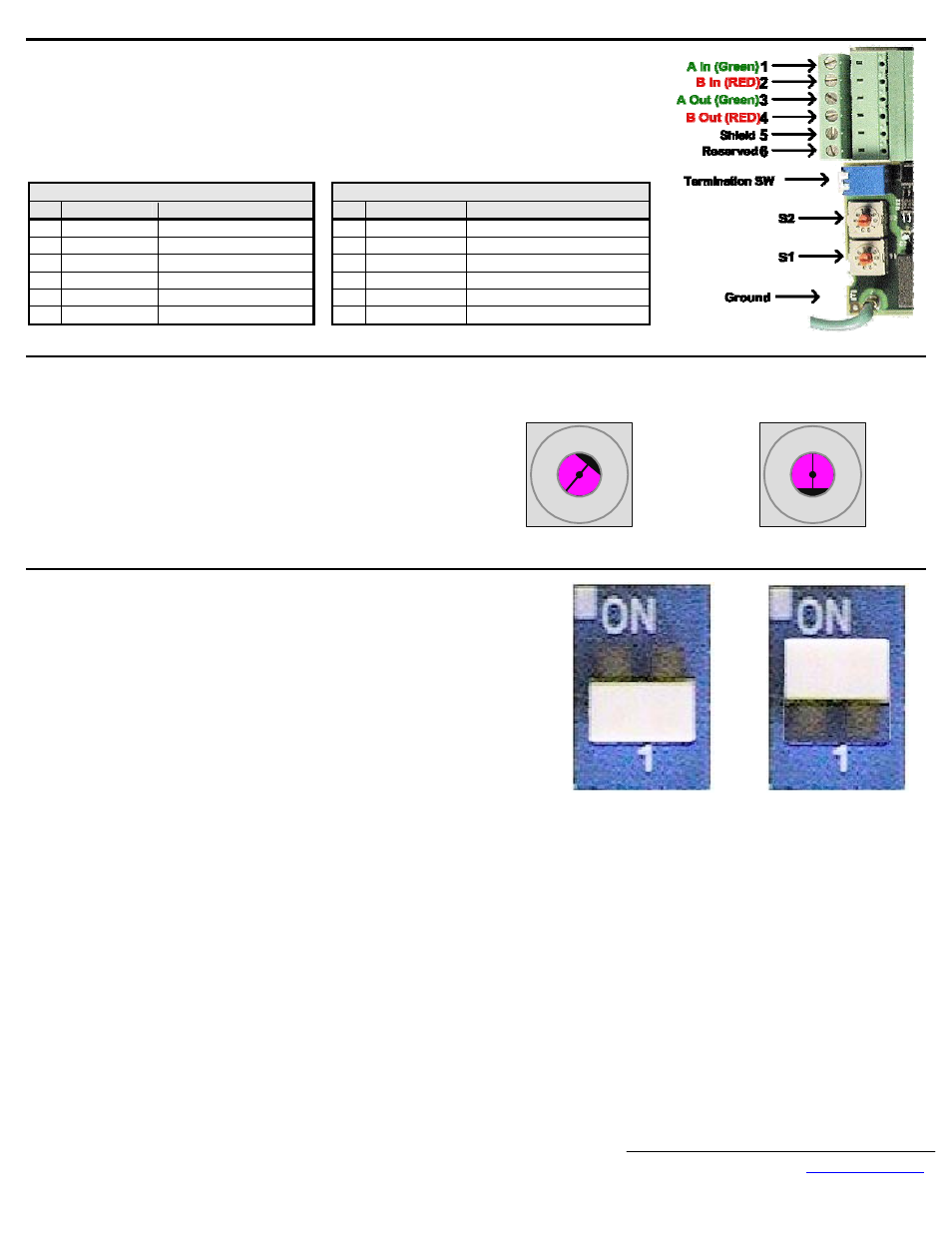
Connect the drive to the Profibus-DP communication network.
Connect the Profibus-DP network cable as shown in the figure to the right.
The cable shield must be contiguous between the beginning and end of any network segment. It is recommended
that the shield of the in cable and the out cable be twisted together. Do not connect the shield to the shield
connector, rather fold it back and secure it to the cable.
Use the pluggable connector that came with the CM061 Profibus-DP Option. The pluggable connector contains a
circuit board that remaps the terminal connections. Do not use an alternate connector. Damage to the CM061
Profibus-DP Option and/or associated network devices could be damaged if an alternate connector is used.
Plug Socket
Pin
Description
Definition
Pin
Description
Definition
1
A In (Green)
Negative
1
Reserved
No Connection
2
B In (Red)
Positive
2
Reserved No
Connection
3
A Out (Green)
Negative
3
A In/Out (Green)
Negative
4
B Out (Red)
Positive
4
B In/Out (Red)
Positive
5 Shield
Shield
5 Shield
Shield
6 Reserved
No
Connection
6 Reserved
No
Connection
Set the node address.
Set the node address for the drive by setting the 10‘s digit with S2
and the 1’s digit with S1.
All devices on the network must have unique node addresses. Check
the network layout to verify that the node address selected is unique
and falls between 3 – 99.
Node addresses 0 and 1 are typically reserved for master controllers.
Node address 2 is typically reserved for diagnostic equipment.
Set network termination.
If this drive is either the first or the last device on the network, including any PLC and/or
Profibus-DP Master, and active termination is not used, set the termination resistor switch to
ON.
If this device is not the first or last device on the network or active termination is used, set
the termination resistor switch to OFF.
Active termination is the recommended termination method and is required for networks
operating above 1.5Mbps. Active termination will eliminate the possibility of network failure
due to the removal of a terminated device.
The Siemens Profibus Terminator part number is 6ES7 972-0DA00-0AA0.
Address = S2 (x10) + S1
Example: Set node address to 15
Set address switch 2 to "1"
Set address switch 1 to "5"
0 1
2
3
45
8
7
6
9
S2
0 1
2
3
45
8
7
6
9
S1
OFF
ON