Yaskawa CM061 User Manual
Page 8
Yaskawa Electric America, Inc. –
www.yaskawa.com
IG.G5HHP.12 Page 8 of 9
Date: 11/06/06 Rev: 06-11
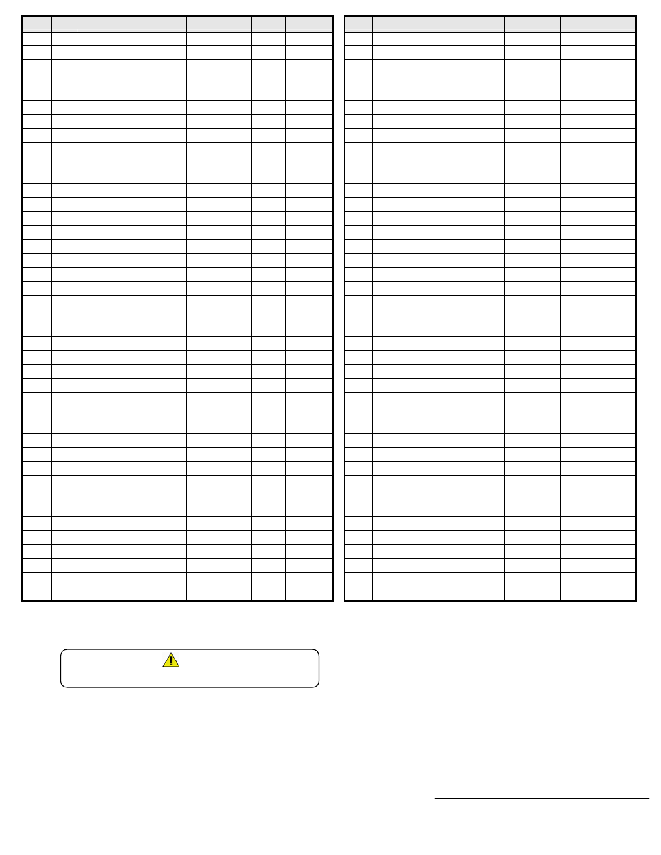
Name Addr
Text
Limits
Default
Cntrl Met
__
Name Addr
Text
Limits
Default Cntrl Met
H1-03
402
DI Terminal 13 Function Select
0 ~ 77h
3
L3-03
48A Stall Prevention Accel CHP Limit
0 ~ 100
50
H1-04
403
DI Terminal 14 Function Select
0 ~ 77h
4
L3-04
48B
Stall Prevention Decel Select
0 ~ 2
1
H1-05
404
DI Terminal 15 Function Select
0 ~ 77h
6
L3-05
48C
Stall Prevention Run Select
0 ~ 2
1
H1-06
405
DI Terminal 16 Function Select
0 ~ 77h
8
L3-06
48D
Stall Prevention Run Level
30 ~ 200
160
H2-01
406
DO Terminal 53-57 Function
0 ~ 37h
0
L4-01
490
Speed Agree Level
0.0 ~ 150.0
0.0
H2-02
407
DO Terminal 19-50 Function
0 ~ 37h
1
L4-02
491
Speed Agree Width
0.0 ~ 20.0
2.0
H2-03
408
DO Terminal 20-50 Function
0 ~ 37h
2
L4-03
492
Speed Agree Detection Level
0.0 ~ 150.0
0.0
H3-01
409 AI Terminal 36 Signal Type Select
0 ~ 1
0
L4-04
493
Speed Agree Detection Width
0.0 ~ 20.0
2.0
H3-02
40A
AI Terminal 36 Gain
0.0 ~ 100.0
100.0
L4-05
494
Reference Loss Detection Select
0 ~ 1
0
H3-03
40B
AI Terminal 36 Bias
-100.0 ~ +100.0
0.0
L5-01
495
Number of Auto Restarts Select
0 ~ 10
0
H3-04
40C AI Terminal 42 Signal Type Select
0 ~ 1
0
L5-02
496
Auto Restart Fault Select
0 ~ 1
0
H3-05
40D
AI Terminal 42 Function Select
1 ~ 1Fh
0
L6-01
498
Torque Detection Select 1
0 ~ 4
0
H3-06
40E
AI Terminal 42 Gain
0.0 ~ 100.0
100.0
L6-02
499
Torque Detection Level 1
0 ~ 300
150
H3-07
40F
AI Terminal 42 Bias
-100.0 ~ +100.0
0.0
L6-03
49A
Torque Detection Time 1
0.0 ~ 10.0
0.1
H3-08
410 AI Terminal 39 Signal Type Select
0 ~ 2
2
L6-04
49B
Torque Detection Select 2
0 ~ 4
0
H3-09
411
AI Terminal 39 Function Select
1 ~ 1Fh
1F
L6-05
49C
Torque Detection Level 2
0 ~ 300
150
H3-10
412
AI Terminal 39 Gain
0.0 ~ 100.0
100.0
L6-06
49D
Torque Detection Time 2
0.0 ~ 10.0
0.1
H3-11
413
AI Terminal 39 Bias
-100.0 ~ +100.0
0.0
L7-01
49E
Forward Torque Limit
0 ~ 300
200
OLV, FV
H3-12
414
AI Terminals Filter Time
0.00 ~ 2.00
0.00
L7-02
49F
Reverse Torque Limit
0 ~ 300
200
OLV, FV
H4-01
415
AO Terminal 45 Function Select
1 ~ 33h
2
L7-03
4A0
Forward Regen Torque Limit
0 ~ 300
200
OLV, FV
H4-02
416
AO Terminal 45 Gain
0.00 ~ 2.50
1.00
L7-04
4A1
Reverse Regen Torque Limit
0 ~ 300
200
OLV, FV
H4-03
417
AO Terminal 45 Bias
-10 ~ +10
0.0
L8-01
4A4
DB Resistor Protection Select
0 ~ 1
0
H4-04
418
AO Terminal 48 Function Select
1 ~ 33h
3
L8-02
4A5
OH Pre-Alarm Level
50 ~ 110
95
H4-05
419
AO Terminal 48 Gain
0.00 ~ 2.50
0.50
L8-03
4A6
OH Pre-Alarm Select
0 ~ 3
3
H4-06
41A
AO Terminal 48 Bias
-10.0 ~ +10.0
0.0
L8-05
4A8
Input Phase Loss Select
0 ~ 1
0
H4-07
41B
AO Terminal Signal Type Select
0 ~ 1
0
L8-07
4AA
Output Phase Loss Select
0 ~ 1
1
H5-01
41C
Modbus Node Address
0 ~ 20
1F
o1-01
500
User Monitor Select
4 ~ 33
6
H5-02
41D
Modbus Baud Rate Select
0 ~ 3
3
o1-02
501
Power-On Monitor Select
1 ~ 4
1
H5-03
41E
Modbus Parity Select
0 ~ 2
0
o1-03
502
Display Scaling Select
0 ~ 39999
0
H5-04
41F
Serial Fault Stopping Method
0 ~ 3
3
o1-04
503
V/f Pattern Unit Select
0 ~ 1
0
H5-05
420
Serial Fault Detection Select
0 ~ 1
1
o1-05
504
Modbus Address Display Select
0 ~ 1
6
L1-01
480
Motor Overload Fault Select
0 ~ 1
1
o2-01
505
Local/Remote Key Select
0 ~ 1
1
L1-02
481
Motor Overload Time Constant
0.1 ~ 5.0
1.0
o2-02
506
Stop Key Function Select
0 ~ 1
1
L2-01
482
Power Loss Detection Select
0 ~ 2
0
o2-03
507
User Initialize Default Select
0 ~ 2
0
L2-02
483
Power Loss Ride-Thru Time
0.0 ~ 2.0
1.0
o2-04
508
Drive Model kVA Select
0 ~ FFh
4400
L2-03
484
Minimum Baseblock Time
0.0 ~ 25.5
10.0
o2-05
509
Operator MOP Function Select
0 ~ 1
0
L2-04
485
Voltage Recovery Ramp Time
0.0 ~ 5.0
3.0
o2-06
50A
Operator Detection Select
0 ~ 1
1
L2-05
486
Undervoltage Detection Level
300 ~ 420
380
o2-07
50B
Elapsed Time Initial Setting
0 ~ 65535
0
L2-06
487
KEB Decel Time
0.0 ~ 100.0
0.0
o2-08
50C
Elapsed Time Function Select
0 ~ 1
0
L3-01
488
Stall Prevention Accel Select
0 ~ 2
1
o2-09
50D
Initialization Mode Select
0 ~ 2
1
L3-02
489
Stall Prevention Accel Level
0 ~ 200
150
Note: 1: Default values were determined through a 2-wire reset on drive model 4400. Default values may be different for different drive models.
2: Use address FFDDh for the ACCEPT command.
3: Use address FFFDh for the ENTER command.
CAUTION!
Limit the use of the ENTER command. The drive has limited writes when using
the ENTER command.