V7 devicenet™ with adr option kit cm013 – Yaskawa CM013 User Manual
Page 2
Yaskawa Electric America, Inc. –
www.yaskawa.com
IG.V7.16, Page 2 of 8
Date: 06/15/2007 Rev: 07-06
V7 DeviceNet™ With ADR Option Kit
CM013
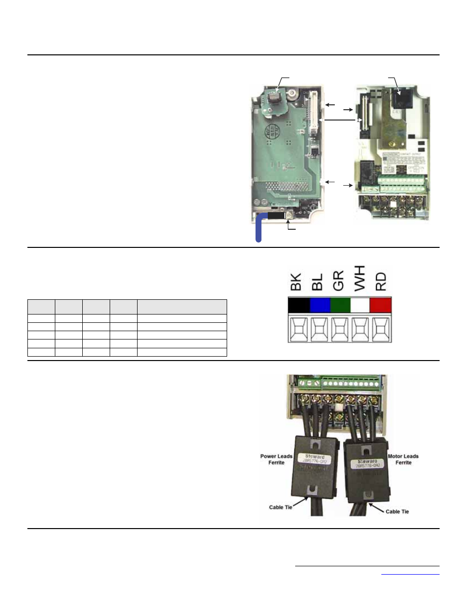
9. Wire the V7 Drive power, motor and I/O terminals prior to mounting the
V7 DeviceNet Option Kit, as the option will obscure the terminals when
mounted.
10. Mount the V7 DeviceNet Option Kit on the V7 Drive.
a. Connect a ground wire of appropriate length from the ground wires
provided to the ground terminal on the back of the DeviceNet Option
CM013.
b. Connect the other end of the ground wire to the V7 drive ground
terminal.
c. Align the CN1 connector on the back of the option with its mating CN2
connector on the front of the V7 drive.
d. Simultaneously align connector CN3 (male RJ-45) on the back of the
option with connector CN1 (female RJ-45) on the front of the V7 drive.
e. Align the tabs on the option with their corresponding slots on the front of
the V7.
f.
Press the option and the V7 drive together until the tabs lock into their
associated slots.
g. Secure the option to the V7 by tightening the locking screw at the top-
center of the option.
11. Network Connection
Connect the DeviceNet cable to the DeviceNet connector as shown. If the drive is
the last device on a network segment make sure to install the terminating resistor
(120
Ω, 1%, metal film, 1/4W) between the CAN terminals 2 (Blue) and 4
(White).
12. Connect the Ferrites to the V7 Power and Motor Leads
Attach the provided ferrites (Steward 28A5776-0A2) to the V7 drive motor and
power leads as close to the V7 Drive terminals as possible (typically within one
foot). Secure the ferrites to the motor and power leads with the provided cable
ties. If the ferrites cannot be mounted in your installation, please contact Yaskawa
for application assistance.
CN1 - CN2
Tab
CN3 - Male RJ45
Connector
CN1 - Female
RJ45 Connector
Slot
Tab
Slot
E
Ground Terminal
Ground Wire
Terminal
Color
Name
Wire
Color
Description
1
Black
V-
Black
Network Common
2
Blue
CAN_L
Blue
CAN Data Low
3
Green
Shield
Green
Cable Shield
4
White
CAN_H
White
CAN Data High
5
Red
V+
Red
+24VDC