V7 devicenet™ with adr option kit cm013 – Yaskawa CM013 User Manual
Page 5
Yaskawa Electric America, Inc. –
www.yaskawa.com
IG.V7.16, Page 5 of 8
Date: 06/15/2007 Rev: 07-06
V7 DeviceNet™ With ADR Option Kit
CM013
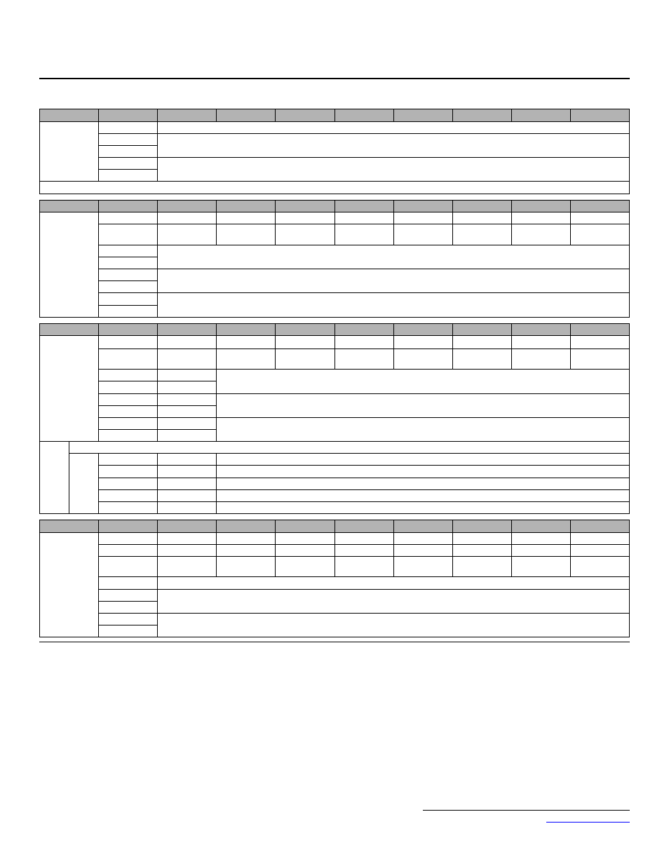
20. Yaskawa Supported Input Instances
Instance
Byte
Bit 7
Bit 6
Bit 5
Bit 4
Bit 3
Bit 2
Bit 1
Bit 0
100 (64h)
Modbus
Message
5 Bytes
0
Function Code (Only Modbus functions register read (03h) and register write (10h) are supported)
1
Register Number
2
3
Data
4
Note: Refer to output assembly instance 150 (96h) for response.
Instance
Byte
Bit 7
Bit 6
Bit 5
Bit 4
Bit 3
Bit 2
Bit 1
Bit 0
101 (65h)
Standard
Control
8 Bytes
0
–
Terminal S7
Terminal S6
Terminal S5
Terminal S4
Terminal S3
Run Reverse
Run Forward
1
Terminal
P2-PC
Terminal
P1-PC
Terminal
MA~MC
–
–
–
Fault Reset
External Fault
2
Speed Reference (Scaled by Parameter n152) (U-01)
3
4
Reserved
5
6
Reserved
7
Instance
Byte
Bit 7
Bit 6
Bit 5
Bit 4
Bit 3
Bit 2
Bit 1
Bit 0
105 (69h)
Enhanced
Control/
Modbus
Message
8 Bytes
0
-
Terminal S7
Terminal S6
Terminal S5
Terminal S4
Terminal S3
Terminal S2
Terminal S1
1
Terminal
P2-PC
Terminal
P1-PC
Terminal
MA~MC
–
Function Bit
2
1
Function Bit
1
1
Fault Reset
External Fault
2
Speed Reference (Scaled by Parameter n152) (U-01)
3
4
Register Number
5
6
Data
7
Note:
Refer to output assembly instance 155 (9Bh) for response.
1
Bit 1
Bit 2
Function Description
0
0
None
0
1
Read Register
1
0
Write Register
1
1
No Function
Instance
Byte
Bit 7
Bit 6
Bit 5
Bit 4
Bit 3
Bit 2
Bit 1
Bit 0
107 (6Bh)
Standard DI/
DO Control
8 Bytes
0
–
Terminal S7
Terminal S6
Terminal S5
Terminal S4
Terminal S3
Terminal S2
Terminal S1
1
–
–
–
–
–
–
Fault Reset
External Fault
2
–
–
Terminal
P2-PC
Terminal
P1-PC
Terminal
MA~MC
–
–
–
3
Reserved
4
Analog Output Terminal AM Refer to n066 for range and setting.
5
6
Speed Reference (Scaled by Parameter n152) (U-01)
7