Yaskawa VS-616G5 DeviceNet Communication Interface Card SI-M2 User Manual
Page 13
VS-616G5 Option Instruction Manual: DeviceNet™ Communication Interface Card SI-M2
Page 13
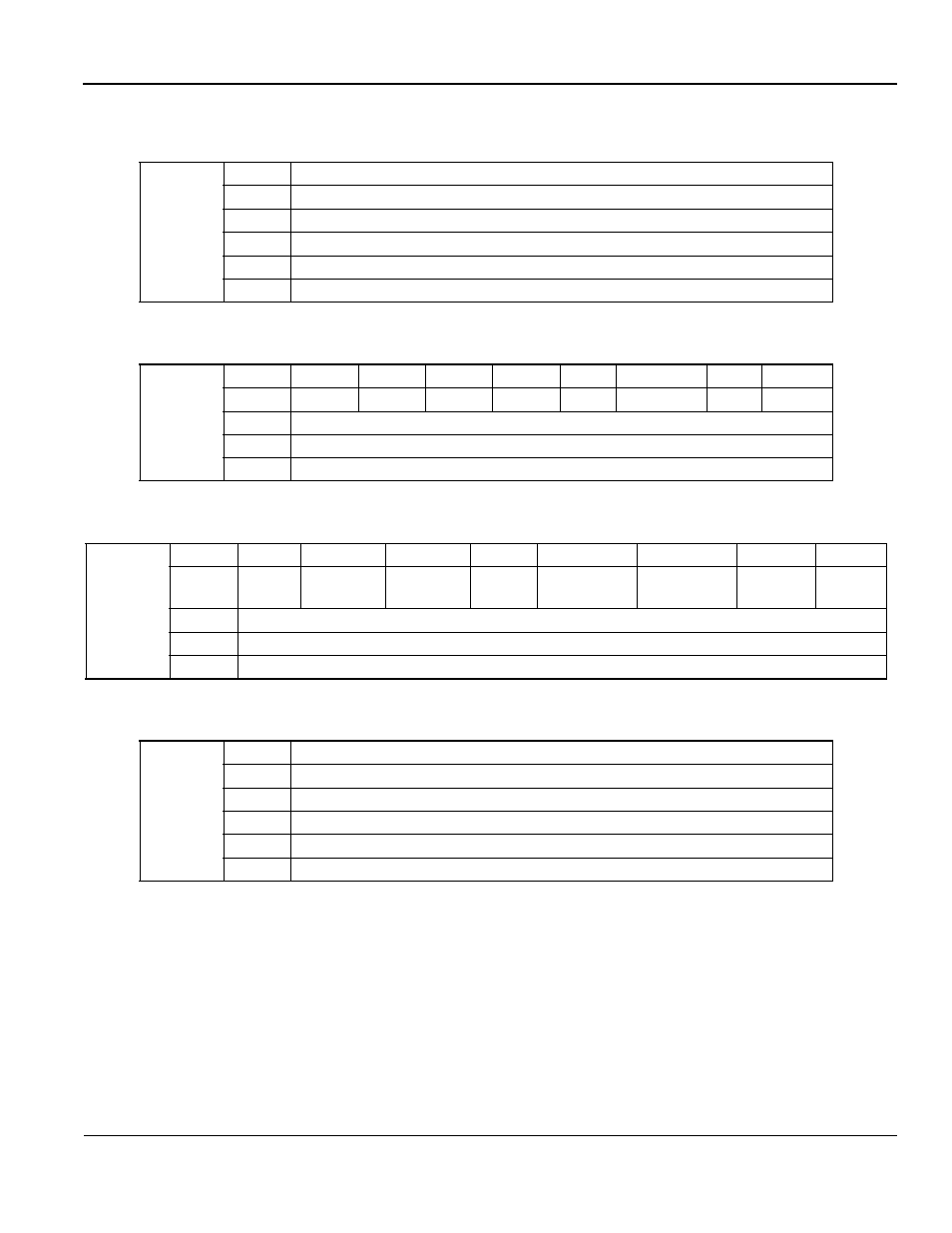
I/O assembly instance settings are configured through the digital operator at menus P1-03 and P1-04. Assem-
blies 100 and 110 are “vendor-specific” Yaskawa assemblies. They are designed to act much like the standard
network communications already active in the G5. Individual registers can be addressed in a read or write
manner allowing access to every configurable parameter. Assembly numbers 100 and 110 must be used to-
gether otherwise an OPE02 error will occur. Please note that these assemblies use the Motorola High-byte
Low-byte addressing versus the normal DeviceNet
Low-byte High-byte addressing.
G5 Standard Communications
Output
Instance
100
Byte
G5 standard command message format
0
Function Code
1
Register Number (High Byte)
2
Register Number (Low byte)
3
Register Data (High byte)
4
Register Data (Low byte)
DeviceNet
Basic Speed Control
Input
Instance
70
Byte
Bit 7
Bit 6
Bit 5
Bit 4
Bit 3
Bit 2
Bit
Bit 0
0
—
—
—
—
—
Running 1
—
Faulted
1
—
2
Speed Actual (Low byte)
3
Speed Actual (High byte)
DeviceNet
Extended Speed Control
Input
Instance
71
Byte
Bit 7
Bit 6
Bit 5
Bit 4
Bit 3
Bit 2
Bit
Bit 0
0
At Spd
Ref From
Net
Ctrl From
Net
Ready
Running 2
(Rev)
Running 1
(Fwd)
Warning
Faulted
1
—
2
Speed Actual (Low byte)
3
Speed Actual (High byte)
G5 Standard Communications
Input
Instance
110
Byte
G5 standard response message format
0
Function Code
1
Register Number (High Byte)
2
Register Number (Low byte)
3
Register Data (High byte)
4
Register Data (Low byte)