Yaskawa VS-616G5 DeviceNet Communication Interface Card SI-M2 User Manual
Page 5
Advertising
VS-616G5 Option Instruction Manual: DeviceNet™ Communication Interface Card SI-M2
Page 5
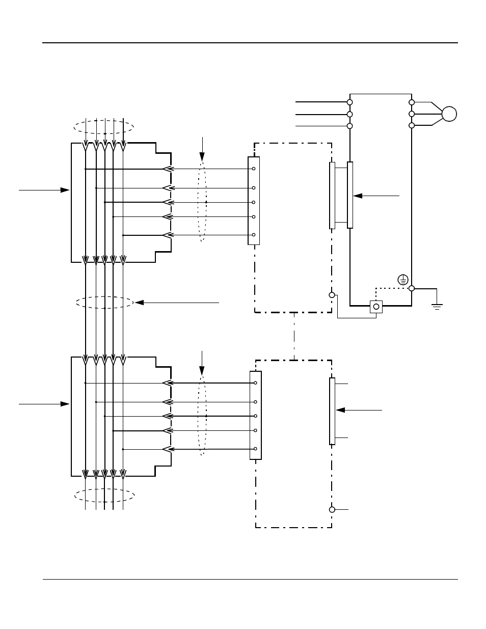
INTERCONNECTION DIAGRAM
Fig. 4 shows the interconnection between the inverter, the DeviceNet
Communication Interface
Card SI-M2, and peripheral equipment:
Inverter
L1(R)
L2(S)
L3(T)
U(T1)
V(T2)
W(T3)
M
VS-616G5
2CN(60P)
Three phase
power supply
SI-M2
12
1
2
4
5
1
2
4
5
SI-M2
TB1
(E)
(E)
Fig. 3 SI-M2 Interconnection Diagram
3
3
TB1
Network
Trunk Cable
Cable
2CN(60P)
Drop Cable
V-
CAN-
Shield
CAN+
V+
V-
CAN-
Shield
CAN+
V+
Power for V+ and V-
comes from the network
Black
Blue
Shield
White
Red
Black
Blue
Shield
White
Red
DeviceNet
™
Drop Cable
DeviceNet
™
DeviceNet
™
Network
Trunk
DeviceNet
™
Network
Trunk
DeviceNet
™
Cable
Note:
power supply.
T Connector
DeviceNet
™
T Connector
DeviceNet
™
Advertising