Jordan Valve Mark 17X Series Flameproof Smart Positioner User Manual
Page 2
M
ark
17X S
erieS
F
laMeprooF
S
Mart
p
oSitionerS
-2-
Linear Installation, Continued
2.
Attach the positioner and mounting bracket to
the actuator yoke – DO NOT FULLY TIGHTEN
FASTENERS COMPLETELY
3.
Connect the positioner feedback lever to the
actuator clamp. The gap on the feedback lever
is 6.5mm. The connection pins
outer diameter should be less than 6.3 mm.
4.
Temporarily connect supply pressure to the
actuator. Supply enough pressure to to the
actuator in order to position the actuator clamp
at 50% of the total valve stroke.
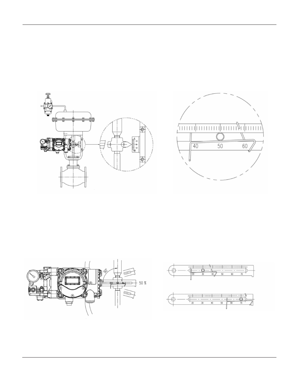
5.
Insert a connection pin into the feedback lever.
The pin should be inserted when the actuator
clamp is at 50% of the total valve stroke.
Feedback lever, connection pin, and spring connections detail
6.
Ensure feedback lever is parallel to the ground
at 50% of the valve stroke. Make adjustments to
the bracket or feedback link bar as required.
Improper installation may cause poor
linearity and may create unnecessary hunting
during the operation.
7.
Check the valve stroke. The stroke marks are
indicated on the feedback lever of the
Mark 17X positioner. Position the
connection pin at the number on the feedback
lever which corresponds to the desired valve
stroke. Adjustments may be made by moving
the bracket, the connection pin, or both.
Pin insertion when valve stroke is
30mm (up) and 70mm (bottom)