Nstallation, Otary – Jordan Valve Mark 17X Series Flameproof Smart Positioner User Manual
Page 3
-3-
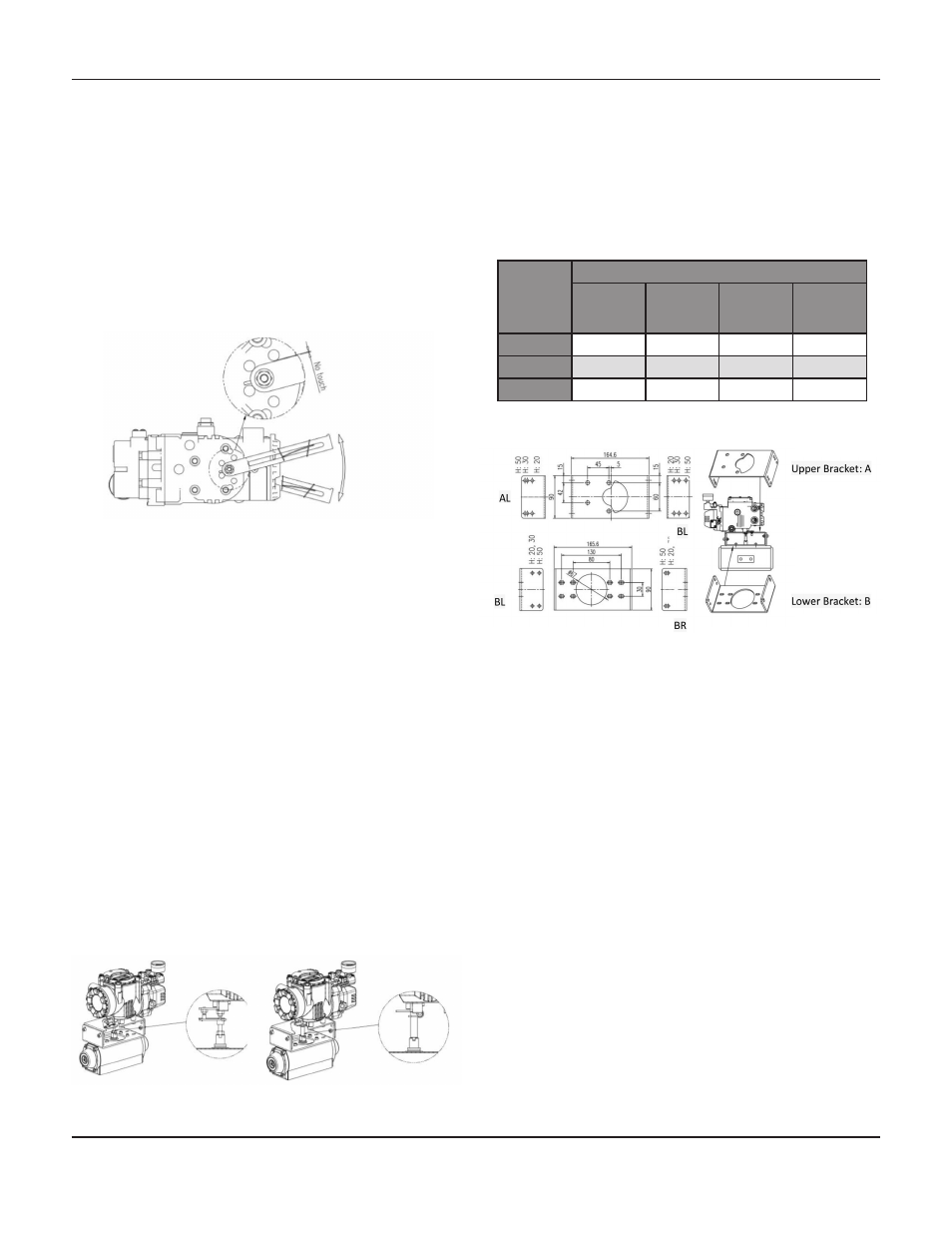
Bracket Information:
The supplied standard bracket contains two com-
ponents. The bracket may be used for both fork
lever type and NAMUR lever type configurations.
The bracket is designed to fit on the actuator with a
20mm stem height (H). Should the stem height be
30mm or 50mm, the bracket must be adjusted as
required.
Actuator
Stem
Height
(H)
Bolt Hole Markings
A-L
B-L
A-R
B-R
20 mm
H: 20
H: 20, 30
H: 20
H: 20, 30
30 mm
H: 30
H: 20, 30
H: 30
H: 20, 30
50 mm
H: 50
H: 50
H:50
H: 50
Linear Installation, Continued
8.
After installing the positioner, operate the
valve from 0% to 100% stroke by using direct
air to the actuator (manual position). At both
0% and 100% the feedback lever should not
touch the lever stopper, which is located on the
back of the positioner. Should the feedback
lever touch the stopper, adjustments may be
required to install the positioner further away
from the actuator yoke.
9.
After installation and adjustment have been
made, complete by tightening the bolts on the
bracket, feedback lever, and the
connection pin.
I
nstallatIon
- r
otary
Mark 17X Rotary Installation
The Mark 17X Rotary Smart Positioner should be in-
stalled on rotary motion valves, such as ball or butterfly
type valves which use a rack and pinion, scotch yoke,
or other type of actuator which uses 90 degree rotation.
Prior to installation have the following items available:
-
Mark 17X Positioner
-
Fork Lever and Lever Spring
-
Standard rotary bracket (supplied)
-
Qty. 4, Hex Head Bolts (M8x1.25P)
-
Qty. 4, M8 Flat Washers
1.
Check actuator stem height and adjust as
required.
2.
Attach the bracket to the actuator. Use lock
washers to prevent the bolts from loosening from
vibrations.
3.
Set the rotation position of the actuator stem to
0%. For single acting actuators, with
no supply pressure to the actuator, the stem will
be at 0%. For double acting actuators,
check the actuator stem rotation
direction – clockwise or counter clockwise- by
supplying pressure to the actuator.
M
ark
17X S
erieS
F
laMeprooF
S
Mart
p
oSitionerS