60s m, 30d m, Ac side) – Magnum Energy Mini Magnum Panel (MMP Series) User Manual
Page 52: Enclosure, Odels
Page 43
©
2013 Magnum Energy, Inc.
Installation
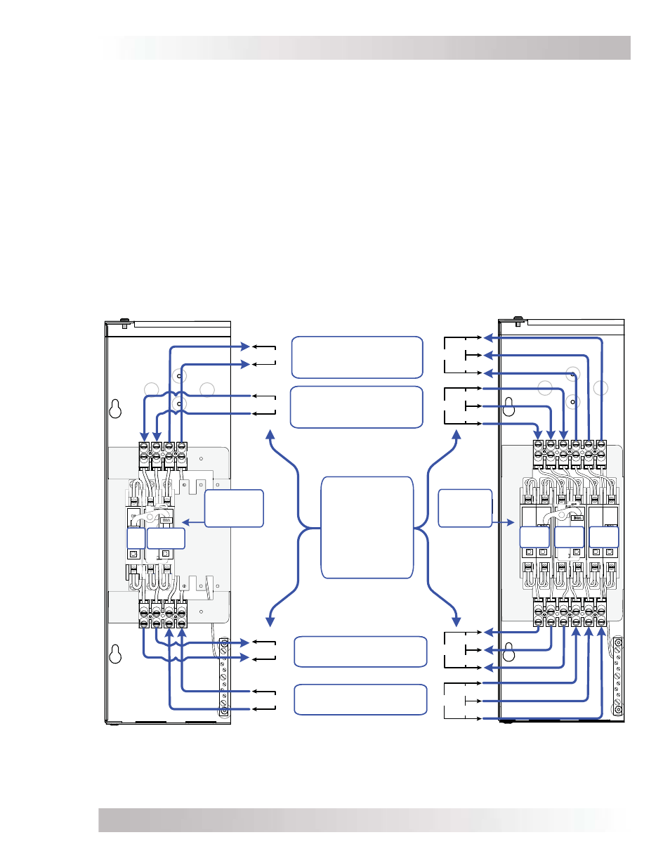
Figure 2-26, AC Voltage Checks
120V
120V
120V
240V
120V
120V
240V
120V
120V
240V
120V
120V
240V
120V
120V
120V
I
NVERTER
I
NPUT
T
ERMINALS
(
TO
INVERTER
’
S
AC
INPUT
)
INV
BYP
INV
OUT
INV
IN
INV IN /
INV OUT
INV
BYP
U
SE
AN
AC
VOLTMETER
TO
READ
VOLTAGE
IN
AND
OUT
OF
THE
MMP
ENCLOSURE
I
NVERTER
O
UTPUT
T
ERMINALS
(
FROM
INVERTER
’
S
AC
OUTPUT
)
MMP
XXX
-60S
M
ODELS
MMP
XXX
-30D
M
ODELS
MMP
ENCLOSURE
(AC SIDE)
AC O
UTPUT
T
ERMINALS
(
TO
INVERTER
LOADS
)
AC I
NPUT
T
ERMINALS
(
FROM
UTILITY
OR
GENERATOR
)
AC
BREAKERS
(-60S Models)
AC
BREAKERS
(-30D Models)
6. Apply power from an external AC source (utility or AC generator) to the AC Input Terminals.
a. Connect an AC voltmeter to the AC Input Terminals and verify that the AC voltage from
the external AC source is present. Connect the AC voltmeter to the AC Output Terminals
and check that the external AC source power is passing thru the INV BYP (Inverter Bypass)
breaker by verifying the AC source voltage present earlier is also present on the AC Output
Terminals.
7. Turn ON the INV OUT
2
and INV IN breaker(s) in the MMP enclosure.
a. Ensure the AC source power is passing thru the INV IN (Inverter Input) breaker by verifying
the AC source voltage present earlier (in Step 6) is also present on the AC Output Terminals.
8. After all the AC voltage checks pass, install the front cover and manually open and close all
circuit breakers, checking for correct alignment and free operation.
If all the steps pass, the MMP enclosure is ready for use. If the any of the steps fails, refer to
Installation section and recheck your wiring connections and/or refer to the Troubleshooting section
for your inverter.