A3 installing a battery monitor, Appendix a - optional equipment and accessories – Magnum Energy Mini Magnum Panel (MMP Series) User Manual
Page 60
Page 51
©
2013 Magnum Energy, Inc.
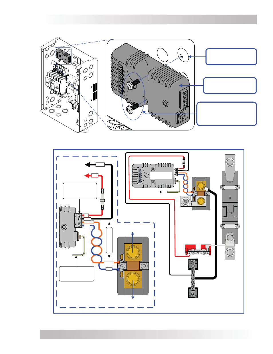
Appendix A - Optional Equipment and Accessories
Figure A3-2, Wiring the Sense Module and DC Shunt
Figure A3-1, Mounting the Sense Module
A3 Installing a Battery Monitor
DC Fuse (2 amps)
To DC
Positive Busbar
To DC
Negative Busbar
orange
blue
black
red
black
red
Twisted-pair cable
4-Port Terminal Block
(can be removed, and
each port accepts
30 to 12 AWG wire).
Communications Cable
(To Network port on
Magnum inverter)
blue
orange
To Battery Bank
To Inverter/Loads
Close-up of wiring
the ME-BMK
Sense Module
(from ME-BMK)
DC Shunt
(in MMP Enclosure)
Battery Positive
Busbar
(in MMP Enclosure)
DC Negative Busbar
(in MMP Enclosure)
To Network Port
M
OUNTING
D
IMPLES
W
/
#8
SCREW
HOLES
(
X
2)
S
ENSE
M
ODULE
(
PART
OF
ME-BMK-NS)
T
WO
#8
X
1/2”,
T15 T
ORX
DRIVE
S
CREWS
(
PROVIDED
&
SCREWED
INTO
THE
TWO
MOUNTING
DIMPLES
)