Operating instructions fig.2 – Sealey VS925 User Manual
Page 2
Operating Instructions:
NOTE: DEFAULT SETTING IS ZIRCONIA SENSOR MODE. TITANIA SENSOR MUST BE MANUALLY
SELECTED (see below) & THE RICH & LEAN VALUES ARE REVERSED.
3.1 SELECTING TITANIA: to select Titania mode, press the “
+ V
” button while holding the “
+ V” button.
When the tester turns on the Titania LED will illuminate. (fig.2)
NOTE: The engine must be at normal operating temperature and running at 1500-2000RPM to test the O
2
sensor.
The tester is fitted with a wire-piercing clip allowing it to pierce the sensor wires without damage, (the insulation
reforms to its original state after removal).
3.2 Switch on the tester by pressing the “ ” button. Connect the black ground clip to a good
chassis ground, or the negative terminal of the vehicle’s battery. Connect the wire-piercing clip to one of
the sensor wires. The tester can test 1, 2, 3, and 4 sensor wires.
3.3 When testing 2, 3 or 4 wire sensors, the indicator panel (fig.1) will identify which wire you are connected
to.
3.3.1 If the top LED illuminates it indicates the clip is connected to the heater supply voltage.
3.3.2 If the second LED illuminates this indicates a connection to the ECU 5V supply, (applicable in the case
of Titania sensor, where fitted).
3.3.3 The open circuit LED will illuminate when the tester is switched on but not connected to any sensor wires,
if a bad connection is made to any if the sensor wires this LED will stay lit. Once a good connection is
made the LED will go out, and one of the other LED’s will illuminate to indicate which sensor wire is
connected.
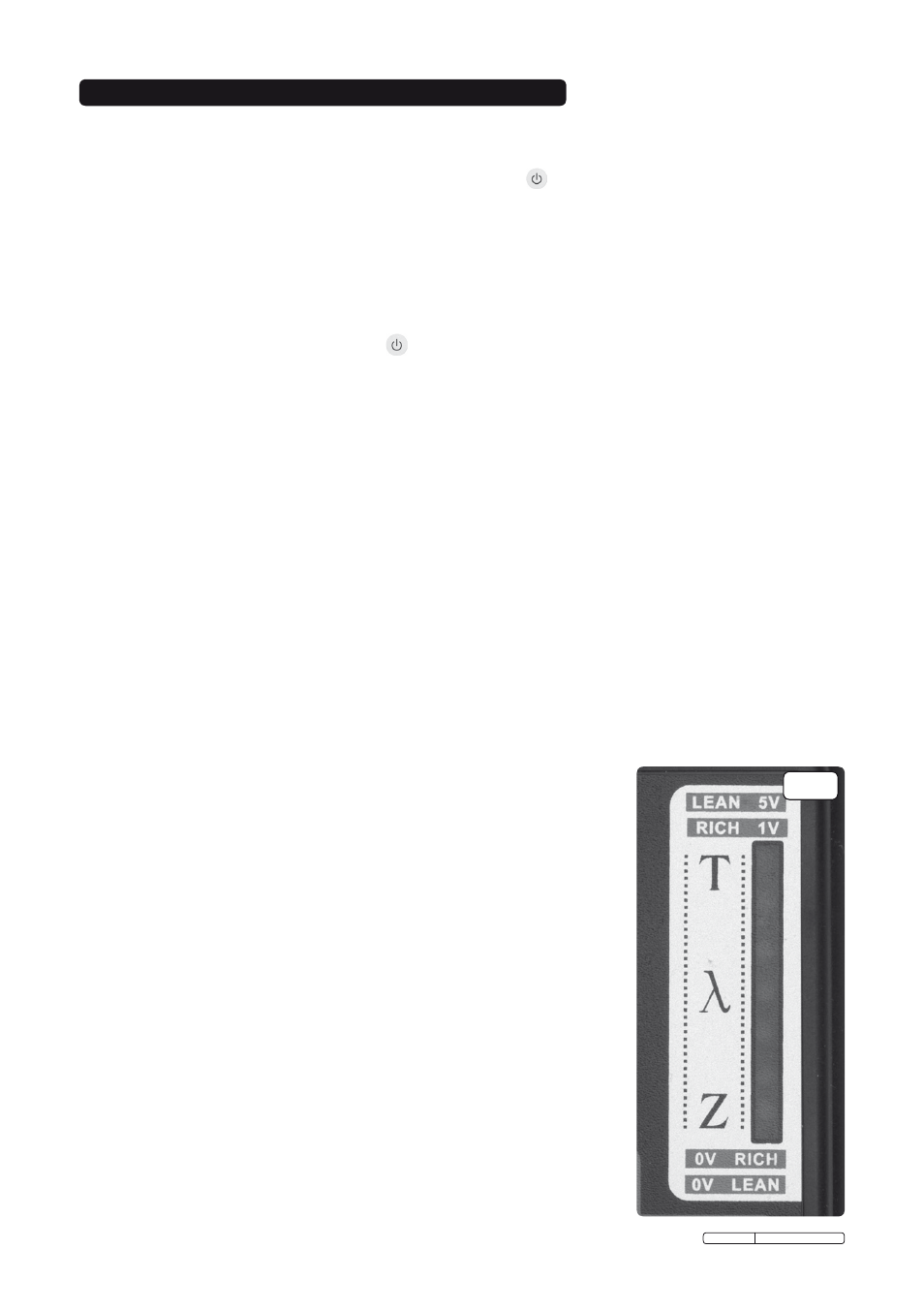
3.4 When connection to the signal wire is made the lights on the vertical display will go out, then the display
LED array In the Lambda window will activate. (fig.2).
3.4.1 A healthy sensor will show movement across the light path and will illuminate the LEDs in the Lambda
window. Once the Lambda window is illuminated ignore any flickering of the LEDs in the indicator panel.
3.5 If connected in default (ZIRCONIA) mode, and only the top 2 lights on the Lambda window are flickering,
this could indicate a Titania sensor. Leaving the unit connected
to the signal wire, switch the unit off and
follow instructions for selecting Titania sensor. If the lights then show movement across the Lambda
window, this would then indicate a Titania sensor on the vehicle.
NOTE! TITANIA SENSOR: RICH & LEAN SIGNALS ARE REVERSED.
3.6 When a Lambda sensor is working correctly in good conditions this will
be shown in the Lambda Window with the LED array illuminating
continuously from lean to rich then back again (see fig.2). This pattern is
repeated constantly. If the sensor is not working correctly or there is a
fault with the ECU this will not occur and the LED array will remain in the
rich or lean sector of the display window, depending on the type of fault.
3.7 To identify the source of the fault, use the simulation feature of the
tester to introduce a rich or lean signal and observe whether this
produces a change in the LED activity on the Lambda window.
Press +V (
Titania, press 0V) on the tester it will transmit a RICH
signal to the ECU.
3.7.1 If the circuit is functioning correctly the mixture will be weakened and
the result should be apparent by a decrease in the engine speed
occurring. Ideally, a four-gas analyser should be used to verify that the
mixture strength varies in response to the false signals introduced.
3.7.2 If there is no reaction it would suggest a wiring/connection problem or
faulty ECU. Faulty fuelling, faulty ignition or faulty management
sensors (located on the engine) could also produce the same effect.
3.7.3 If there is a response to the simulated signal the Lambda sensor should
be checked, cleaned and tested, and replace or substitute if necessary.
Original Language Version
VS925.V2 Issue: 1 - 24/06/10
3. OPERATING INSTRUCTIONS
fig.2