Bt91/1.v2, [email protected] – Sealey BT91/1 User Manual
Page 2
BT91/1.V2 & BT91/2 - 1 - 250505
3.5
LOAD TEST CHART
Load Test Result
Battery Condition
OK - green.
Battery capacity is good. May or may not be fully charged. Check electrolyte specific gravity to determine charge
state. If not fully charged check for charging system fault (para. 3.6) or electrical drain.
Bad or Weak - red,
Battery capacity is unsatisfactory. Battery may be either: (1) defective or (2) partly discharged.
but reading steady.
Check electrolyte specific gravity. If over 1.225 battery is defective. If under 1.225 recharge battery and retest. If
cell-to-cell specific gravity varies by more than 0.025 a cell defect may exist. If charging does not bring specific
gravity to full charge level battery is either sulphated or has lost active material.
Bad or Weak - red,
Battery may be defective. Check no-load voltage. If voltage recovers to 12 volts (6 volts for 6 volt battery) or more
but reading falling after
in a few seconds then battery is probably defective. If voltage recovers slowly battery may only be discharged.
5 secs. load test.
Check electrolyte specific gravity and proceed as above.
3.6
BATTERY VOLTAGE/CHARGE LEVEL
3.6.1
If the load test result indicates a battery fault, allow battery to stabilize for a few minutes and then read the open circuit voltage i.e. meter reading with
knurled knob (fig 1.A) unscrewed.
3.6.2
Compare the reading with the Voltage/Charge table below to get an estimation of the charge level.
Open Circuit Voltage
Charge %
12V/6V battery
11.7/5.8 or lower
0
12.0/6.0
25
12.2/6.1
50
12.4/6.2
75
12.6/6.3 or higher
100
3.6.3
The battery is considered charged at 75% or more. If it failed the load test with this charge it should be
replaced. If the voltage indicates a charge level below 75% then charge the battery and load test again.
If it fails this second test replace it.
3.7
CHARGING SYSTEM
3.7.1
Start engine and allow to reach normal operating temperature.
3.7.2
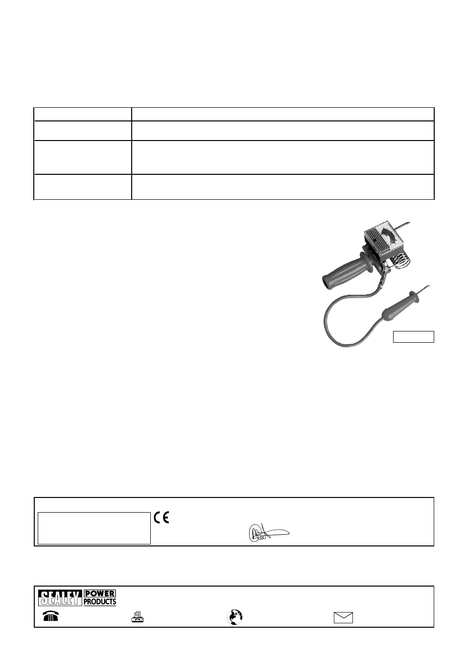
Unscrew the knurled knob (fig 1.A) to isolate the load resistor.
3.7.3
Run engine at 1200 to 1500rpm and note the meter reading, which should be in the green sector within
the yellow area.
3.7.4
Switch on head lights and heater fan (highest speed), meter reading should remain in the green sector.
3.7.5
A reading in the red sector to the left indicates a fault in the charging system which will cause the battery
to be under-charged. A reading in the red sector to the right indicates a fault which will cause the battery to be over-charged.
3.8
STARTER MOTOR
Note:
This test requires that the battery is in good condition and is charged to at least 75% capacity.
3.8.1
Disable ignition system (remove fuse or similar) so that the engine will not start.
3.8.2
Carry out a load test (section 3.2/3.3), if not already done, and note voltage reading.
3.8.3
Unscrew the knurled knob (fig 1.A) to isolate the load resistor.
3.8.4
Operate the starter motor and note the voltage during cranking.
3.8.5
A drop of more than 3 volts (1.5 volts for a 6 volt system) indicates that the starter motor is taking excessive current. This may be due to poor
connections, a faulty motor or the battery being too small for vehicle.
3.8.6
After test reinstate ignition system.
The meter reading, for a healthy battery, should be between 11.5 and 12.5 volts for a 12 volt battery or between 5.5 and 6.5 volts for a 6 volt
battery.
3.4.2
Battery voltage under load
Screw in the knurled knob (fig 1.A) to connect the load resistor (fig 1.B) and then connect the tester to the battery as described above (engine switched
off). DO NOT test for more than 5 seconds.
Compare the meter reading with load test chart (3.5) to determine battery condition.
NOTE: For 12 volt batteries there are two meter scales - the upper for batteries with capacity greater than 40Ah and the lower for those with capacity less than
40Ah.
NOTE: It is our policy to continually improve products and as such we reserve the right to alter data, specifications and component parts
without prior notice. IMPORTANT: No liability is accepted for incorrect use of this equipment. WARRANTY: Guarantee is 12 months from
purchase date, proof of which will be required for any claim. INFORMATION: For a copy of our latest catalogue and promotions call us on
01284 757525 and leave your full name and address, including postcode.
www.sealey.co.uk
01284 757500
01284 703534
Web
Sole UK Distributor, Sealey Group, Bury St. Edmunds, Suffolk.
Declaration of Conformity
We, the sole importer into the UK, declare that the products listed here are in conformity with the following standards and directives.
The construction files for these products are held by the Manufacturer and may be inspected,
by a national authority, upon request to Jack Sealey Ltd.
For Jack Sealey Ltd.
Sole importer into the UK
of Sealey Power Products.
Signed by Mark Sweetman
25th May 2005
BATTERY TESTERS
Models: BT91/1.V2 & BT91/2
93/68/EEC CE Marking Directive
89/336/EEC EMC Directive
BT91/1.V2