Fig. 4 fig. 3 fig. 5, Declaration of conformity – Sealey VS600 User Manual
Page 2
Sole U.K. Distributor, Sealey Group,
Bury St. Edmunds, Suffolk.
NOTE:
It is our policy to continually improve products and as such we reserve the right to alter data, specifications and component parts without prior notice.
IMPORTANT: No responsibility is accepted for incorrect use of this equipment.
WARRANTY: Guarantee is 12 months from purchase, proof of which will be required for any claim.
INFORMATION: For a copy of our latest catalogue and promotions call us on 01284 757525 and leave your full name and address, including postcode.
VS600 - 2 - 110304
4.3.
Dye Injection - A/C system under pressure
4.3.1. It requires a minimum of approximately 450g of coolant to flow through the injector to
ensure that all the dye is transferred to the A/C system. Therefore recover this amount,
or more, from the system.
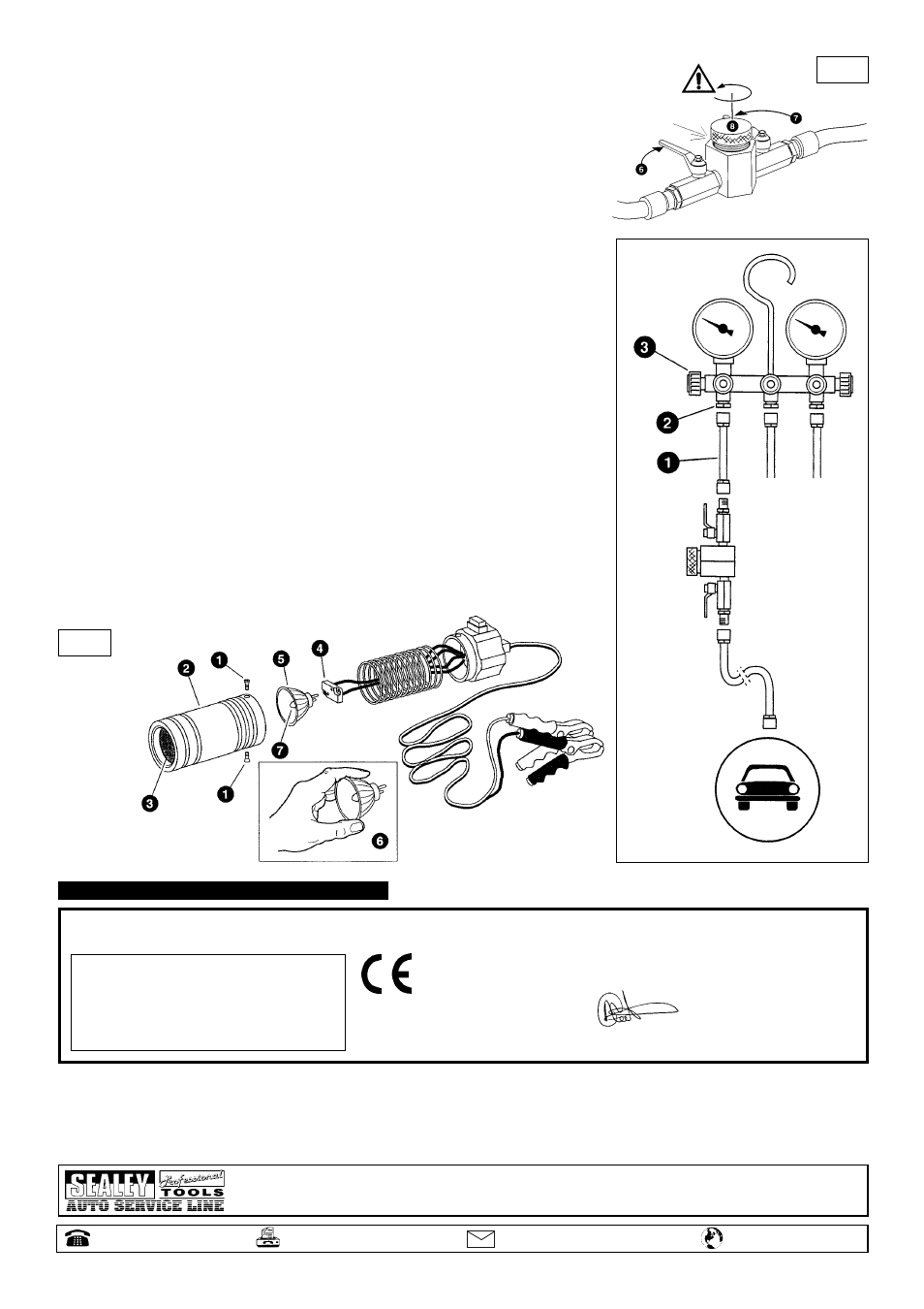
4.3.2. Close the two injector valves (fig. 3.6 & 7).
4.3.3. Warning! The injector is pressurised. Remove the cover (fig. 3.8) slowly and with care.
4.3.4. Pour one bottle of dye (fig. 2.9) into the tank and then screw the cover back on, firmly.
4.3.5. Open the injector valve that is between the equipment and the car (fig. 2.6).
4.3.6. Start the recovery/recycling equipment loading function and immediately open the second
injector valve (fig. 2.7). The air conditioning system will be charged with coolant and dye.
4.3.7. When the required system loading level is reached stop the recovery/recycling equipment.
Leave both injector valves open.
4.4.
Dye Injection with a manometric unit (fig. 4)
The dye injector can also be used with a manometric charging system, as shown in fig. 4.
4.4.1. Connect the injector pipe (1) to the low pressure fitting (2).
4.4.2. Follow the instructions as for use with the recovery/recycling equipment.
4.4.3. To start the coolant flow open the low pressure valve (3) of the manometric unit.
4.5.
Leak detection
Note: Leaks will be more obvious if the UV inspection is carried out in low ambient light.
4.5.1. Run the air conditioning for at least 10 minutes to distribute the dye throughout the
system and then turn off the engine.
4.5.2. Connect the UV lamp to the vehicle battery terminals, or other suitable 12 volt supply,
noting that correct polarity (red clamp to positive terminal) is important.
4.5.3. Wearing the UV safety goggles, point the UV lamp at the area to be inspected and then
press the switch to turn it on. Switch off the lamp while redirecting it to the next
area of interest.
Warning! The lamp gets hot during use. Do not touch the lens, do not place the lamp
near inflammable material and do not return the lamp to the case until it has cooled.
Leaks will become obvious as the dye will fluoresce under the UV light.
4.6.
Bulb replacement (fig. 5)
4.6.1. Remove the two body screws (1) and pull apart the lamp body, taking care not to damage
the lens (3).
4.6.2. Disconnect the bulb (5) from the socket (4).
4.6.3. Fit the new bulb to the socket, ensuring that you do not touch the bulb glass (7). Always
hold the bulb by the outer edge (6). Touching the glass will shorten the life of the bulb.
4.6.4. Reassemble the lamp and refit the two body screws (1).
fig. 4
fig. 3
fig. 5
5. DECLARATION OF CONFORMITY
Declaration of Conformity We, the sole importer into the UK, declare that the product listed below is in conformity with the following
standards and directives.
The construction file for this product is held by the Manufacturer and may be
inspected, by a national authority, upon request to Jack Sealey Ltd.
For Jack Sealey Ltd. Sole importer into the UK of Sealey Professional Tools.
Air Conditioning Leak Detection Kit
Model VS600
89/336/EEC EMC Directive
93/68/EEC CE Marking Directive
21st October 2002
Signed by Mark Sweetman
01284 757500
www.sealey.co.uk
01284 703534
Web