MEDC Weatherproof ResistTel IP User Manual
Page 19
Short Manual ResistTel IP2 / IP152
Page 19
ExResistTel IP2 / IP154
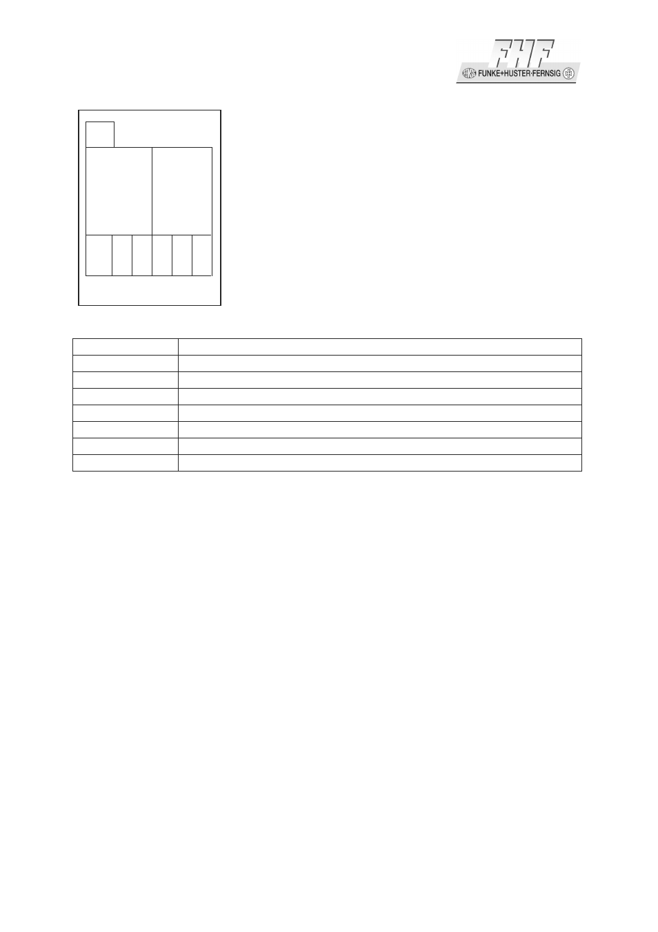
Figure 10: Connection Diagram Relay Module
Connector
Description
K1
Cable to the main board (connection to plug in X12)
1 (relay 1)
Bottom contact relay 1
2 (relay 1)
Middle contact relay 1
3 (relay 1)
Switching contact relay 1
1 (relay 2)
Bottom contact relay 2
2 (relay 2)
Middle contact relay 2
3 (relay 2)
Switching contact relay 2
Table 5: Plug in Connectors and Terminals of the Relay Module
Pay particular attention to the following points if hazardous voltages (>48V) are to
be connected to the relay outputs:
• Cable and cords must be insulated and have to be conducted below the cover.
• The circuits that the relay outputs are connected to must be of the same type;
i.e. both mains, both SELV or both TNV circuits.
• It is not permissible to connect different types of circuits to these relays.
1.5.4
Other Terminals
The terminals 1 – 4 are for connecting a headset. A detailed description is enclosed
in the manual.
The terminals 7 – 13 are reserved for future use and must not be connected.
K1
Relay 1 Relay 2
1 2 3 1 2 3