Page 2 – Whelen AVN1A User Manual
Page 2
Page 2
BLK: Ground
(not used)
RED: +12VDC
WHT/VIO: Scan-Lock™
GRY: SYNC
Single Avenger™ shown
for reference
All switches and fuses
are customer supplied
SP/ST
switch
3A fuse
Cut & cap GRY wire
GRY
BLK
RED
WHT/VIO
(+)
Battery
(-)
Momentary
Switch (N.O.)
BLK: Ground
GRY: SYNC (not used)
RED: +12VDC
WHT/VIO: Scan-Lock™
Single Avenger
shown for reference
™
Butt Splice
Fuse*
*5A Fuse (single Avenger)
10A Fuse (dual Avenger)
(+)
Battery
(-)
GRY
BLK
RED
WHT/VIO
GRY
BLK
WHT/VIO
RED
SP/ST Switch
Momentary Switch
(normally open)
SW1 =
SW2 =
SW1
SW2
SW2
SignalAlert Phase 1 (alt.)
SignalAlert Phase 1 (alt.)
SignalAlert Phase 1 (alt.)
SignalAlert Phase 2 (alt.)
SignalAlert Phase 1 (sim.)
SignalAlert Phase 1 (sim.)
SignalAlert Phase 1 (sim.)
SignalAlert Phase 2 (sim.)
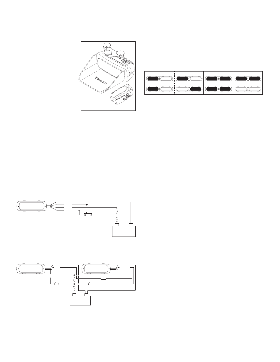
Dash Light can be
mounted two ways
for optional deck
mounting.
Mounting:
CAUTION! Nighttime operation of this product may produce reflected light within the
vehicle! Use with caution!
CAUTION: This product has been designed to rest on top of the vehicle dashboard.
Suction cups are used to prevent lateral movement while the vehicle is in motion.
These suction cups should not be used to suspend this product above the
dashboard.
1. Secure the lower mounting bracket to the
Avenger™ (the Dual Avenger uses two
brackets).
2. Slide the suction cups onto the upper
mounting bracket and secure the upper
mounting bracket onto the lower mounting
bracket.
3. Attach the reflector tape to the visor hood
and secure the visor hood to the unit.
4. With the Avenger resting on the top of the
dashboard, apply the suction cups to the
windshield. Do not locate the Avenger
in any location where it will interfere
with the drivers ability to safely
operate the vehicle. Refer to the safety
warnings on the cover of this manual.
5. Adjust the angle of the Avenger bracket
until the visor hood is in full contact with
the windshield.
There are holes on the upper bracket to be
used if permanent mounting is desired. Using
the upper bracket as a template, mark the
areas where the mounting holes are to be drilled. Secure the unit using the appropriate
hardware (customer supplied).
Wiring:
IMPORTANT AIR BAG WARNING! Do not install this product or route any wires in
the air bag deployment zone of your vehicle. Equipment mounted or located in air
bag deployment zones will damage or reduce the effectiveness of the air bag, or
become a projectile that could cause serious personal injury or death. Refer to your
vehicle owners manual to learn the air bag deployment zones for the vehicle. The
User/Installer assumes full responsibility to determine proper mounting location,
based on providing ultimate safety to all passengers inside the vehicle.
The standard Avenger uses a cigar cord for power connection and no further wiring is
necessary. This cord has a built in Power switch and a Scan-Lock™ pattern selection
momentary switch. The Sync models must be wired as outlined below.
All customer supplied wires that connect to the positive terminal of the battery must
be sized to supply at least 125% of the maximum operating current and FUSED at the
battery to carry that load. DO NOT USE CIRCUIT BREAKERS WITH THIS PRODUCT!
One (1) Sync Avenger (single or double)
1. Extend the RED wire to a Single Pole/Single Throw switch. From this switch, extend a
wire to +12VDC. See the appropriate Parts Diagram for fusing information.
2. Extend the BLACK wire to chassis ground.
3. The GREY wire is not used. Cut & cap this wire.
Flash patterns for both Avengers are listed below.
Synchronizing the Single Avenger - To sync two or more lightheads, configure all
lightheads to display the same Phase 1 pattern. When the lightheads are activated, the
patterns displayed will be synchronized. To configure specific lightheads to alternate their
patterns with other lightheads, advance the pattern of either lighthead to the Phase 2 mode
of the current pattern.
Synchronizing the Dual Avenger - The dual Avenger has 4 unique modes for each
syncable pattern; Alternating Phase 1, Alternating Phase 2, Simultaneous Phase 1 and
Simultaneous Phase 2. In Alternating mode, the left lighthead in a dual Avenger alternates
with the right lighthead. In Simultaneous mode, the left and right lighthead in a dual Avenger
flash simultaneously.
This diagram shows the relationship between two, dual sync’d Avengers. Keep in mind that
all Avengers connected by the Grey wire must be configured to flash the same pattern (as
shown, both Avengers are displaying Signal Alert™).
Two (2) or more Sync Avengers (single or double)
1. Extend the RED wire from each Avenger to a Single Pole/Single Throw switch. From this
switch, extend a wire to +12VDC. See the appropriate Parts Diagram for fusing
information.
2. Extend the BLACK wires from each Avenger to chassis ground.
3. Butt splice the two GREY wires together.
1. SignalAlert™ 75
2. CometFlash® 75
3. DoubleFlash 75
4. SingleFlash 75
5. ComAlert™ 75
6. LongBurst™ 75
7. PingPong™ 75
8. SingleFlash 60
9. SingleFlash 90
10.SingleFlash 120
11. SingleFlash 300
12.DoubleFlash 150
13.ComAlert™150
14.ActionFlash™ 50
15.ActionFlash™ 150
16.ModuFlash™
17.DoubleFlash 120
18.PingPong™ 120
19.TripleFlash™ 75
20.TripleFlash™ 120
21.SigAlert Cal.™
22.Action SF 60/120
23.Action SF120/TF75
24.CalScan™
25.ActionScan™
26.SigAlert Steady™
27.Steady
Flash Patterns - Single Avenger w/Cigar Cord (Model AVN1*)
1. SignalAlert™ 75-PH.1
2. SignalAlert™ 75-PH.2
3. CometFlash® 75-PH.1
4. CometFlash® 75-PH.2
5. DoubleFlash 75-PH.1
6. DoubleFlash 75-PH.2
7. SingleFlash 75-PH.1
8. SingleFlash 75-PH.2
9. ComAlert™ 75-PH.1
10.ComAlert™ 75-PH.2
11. LongBurst™ 75-PH.1
12.LongBurst™ 75-PH.2
13.PingPong™ 75-PH.1
14.PingPong™ 75-PH.2
15.SingleFlash 60
16.SingleFlash 90
17.SingleFlash 120
18.SingleFlash 300
19.DoubleFlash 150
20.ComAlert™150
21.ActionFlash™ 50
22.ActionFlash™ 150
23.ModuFlash™
24.DoubleFlash 120
25.PingPong™ 120
26.TripleFlash™ 75
27.TripleFlash™ 120
28.SigAlert Cal.™
29.Action SF 60/120
30.Action SF 120/TF75
31.CalScan™
32.ActionScan™
33.SigAlert Steady™
34.Steady
Flash Patterns - Single Avenger w/o Cigar Cord (Model AVNS1*)
1. SignalAlert™ 75-ALT
2. SignalAlert™ 75-SIM
3. CometFlash® 75-ALT
4. CometFlash® 75-SIM
5. DoubleFlash 75-ALT
6. DoubleFlash 75-SIM
7. SingleFlash 75-ALT
8. SingleFlash 75-SIM
9. ComAlert™ 75-ALT
10.ComAlert™ 75-SIM
11. LongBurst™ 75-ALT
12.LongBurst™ 75-SIM
13.PingPong™ 75-ALT
14.PingPong™ 75-SIM
15.SSNF 75
16.SingleFlash 60-ALT
17.SingleFlash 60-SIM
18.SingleFlash 90-ALT
19.SingleFlash 90-SIM
20.SingleFlash 120-ALT
21.SingleFlash 120-SIM
22.SingleFlash 300-ALT
23.SingleFlash 300-SIM
24.DoubleFlash 150-ALT
25.DoubleFlash 150-SIM
26.ComAlert™150-ALT
27.ComAlert™150-SIM
28.ActionFlash™ 50-ALT
29.ActionFlash™ 50-SIM
30.ActionFlash™ 150-ALT
31.ActionFlash™ 150-SIM
32.ModuFlash™-ALT
33.ModuFlash™-SIM
34.DoubleFlash 120-ALT
35.DoubleFlash 120-SIM
36.PingPong™ 120-ALT
37.PingPong™ 120-SIM
38.TripleFlash™ 75-ALT
39.TripleFlash™ 75-SIM
40.TripleFlash™ 120-ALT
41.TripleFlash™ 120-SIM
42.SigAlert Cal.™-ALT
43.SigAlert Cal.™-SIM
44.Action SF 60/120-ALT
45.Action SF 60/120-SIM
46.Action SF120/TF75-ALT
47.Action SF120/TF75-SIM
48.CalScan™-ALT/SIM
49.ActionScan™-ALT/SIM
50.SteadyFlash 60
51.SteadyFlash 75
52.SteadyFlash 90
53.SteadyFlash 120
54. Steady & Steady
- Single Split Avenger w/Cigar Cord (Model AVN1#)
Flash Pattern Selection:
To advance to the next flash pattern, press the pattern selection switch for less than 1
second. To cycle backwards to previous patterns, press the pattern selection switch for
more than 1 second.
To reset to the factory default pattern: With power to the lighthead off, press and hold the
pattern selection switch. Turn the lighthead on and keep the pattern selection switch
depressed for at least 5 seconds before releasing.
1. SignalAlert™ 75-PH.1
2. SignalAlert™ 75-PH.2
3. SignalAlert™ 75-PH.3
4. SignalAlert™ 75-PH.4
5. CometFlash® 75-PH.1
6. CometFlash® 75-PH.2
7. CometFlash® 75-PH.3
8. CometFlash® 75-PH.4
9. DoubleFlash 75-PH.1
10.DoubleFlash 75-PH.2
11. DoubleFlash 75-PH.3
12.DoubleFlash 75-PH.4
13.SingleFlash 75-PH.1
14.SingleFlash 75-PH.2
15.SingleFlash 75-PH.3
16.SingleFlash 75-PH.4
17.ComAlert™ 75-PH.1
18.ComAlert™ 75-PH.2
19.ComAlert™ 75-PH.3
20.ComAlert™ 75-PH.4
21.LongBurst™ 75-PH.1
22.LongBurst™ 75-PH.2
23.LongBurst™ 75-PH.3
24.LongBurst™ 75-PH.4
25.PingPong™ 75-PH.1
26.PingPong™ 75-PH.2
27.PingPong™ 75-PH.3
28.PingPong™ 75-PH.4
29.SSNF 75 - PH.1
30.SSNF 75 - PH.2
31.SingleFlash 60-ALT
32.SingleFlash 60-SIM
33.SingleFlash 90-ALT
34.SingleFlash 90-SIM
35.SingleFlash 120-ALT
36.SingleFlash 120-SIM
37.SingleFlash 300-ALT
38.SingleFlash 300-SIM
39.DoubleFlash 150-ALT
40.DoubleFlash 150-SIM
41.ComAlert™150-ALT
42.ComAlert™150-SIM
43.ActionFlash™ 50-ALT
44.ActionFlash™ 50-SIM
45.ActionFlash™ 150-ALT
46.ActionFlash™ 150-SIM
47.ModuFlash™-ALT
48.ModuFlash™-SIM
49.DoubleFlash 120-ALT
50.DoubleFlash 120-SIM
51.PingPong™ 120-ALT
52.PingPong™ 120-SIM
53.TripleFlash™ 75-ALT
54.TripleFlash™ 75-SIM
55.TripleFlash™ 120-ALT
56.TripleFlash™ 120-SIM
57.SigAlert Cal.™-ALT
58.SigAlert Cal.™-SIM
59.Action SF 60/120-ALT
60.Action SF 60/120-SIM
61.Action SF120/TF75-ALT
62.Action SF120/TF75-SIM
63.CalScan™-ALT/SIM
64.ActionScan™-ALT/SIM
65.SteadyFlash 60
66.SteadyFlash 75
67.SteadyFlash 90
68.SteadyFlash 120
69. Steady & Steady
Flash Patterns - Dual Avenger w/o Cigar Cord (Model AVNS2**)
BOLD = California Title XIII Compliant Pattern Italic = SYNC Patterns
NOTE:
Flash Patterns - Dual Avenger w/Cigar Cord (Model AVN2**)