Specifications, Installation, Wiring – Whelen DP2AA User Manual
Page 2: Grey / sync, Operation: white/violet / scan-lock
Page 2
RED / +12V DC
Fuse the RED wire @
2 LIGHT =
4 LIGHT =
6 Light =
8 Light =
3 amps
5 amps
7.5 amps
10 amps
RED / +12V DC
BLK / Ground
BLK / Ground
WHT/VIO / Scan-Lock™
WHT/VIO / Scan-Lock™
GRY / SYNC
GRY / SYNC
Butt Splice
CAUTION! DO NOT LOOK DIRECTLY AT THESE LEDS WHILE THEY ARE ON.
MOMENTARY BLINDNESS AND/OR EYE DAMAGE COULD RESULT!
IMPORTANT WARNING!
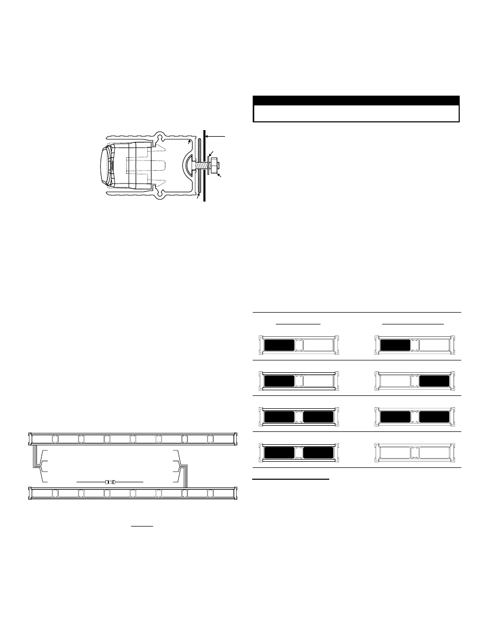
DRIVER SIDE
EXAMPLE: Two, 2 light Dominators™ mounted on the rear deck.
Phase 1 / ALT
Phase 2 / ALT
Phase 1 / SIM
Phase 2 / SIM
PASSENGER SIDE
Phase 1 / ALT
Phase 1 / SIM
Phase 1 / SIM
Phase 1 / ALT
End view of extrusion with endcap removed.
MOUNTING
SURFACE
#10 .631 DIA. X .060
FLAT WASHER
#10-24
ELASTIC
STOP NUT
DISK GASKET
BASE
EXTRUSION
Specifications:
Input Voltage.................................................................................. 12.8 VDC +/- 20%
Input Current for each lighthead / Sim..........................................Peak - .75 Amps
Input Current for each lighthead / Alt .............................................Peak - .3 Amps
For your lightbar’s input current, multiply by the amount of lightheads in your lightbar.
Input Sync................................................................................................ Active Low
Sync Phase............................................................................. Phase I & II @ 400ms
Input Scan-Lock™ .......................................................................+12 VDC @ 20 ma
Installation:
Note: When routing
the wires, it is very
important that you
choose a path that
will keep the wires
away from excessive
heat or any vehicle
equipment that could
compromise the
integrity of the wires
(ex. trunk lids, door
jams, etc.).
Note: Permanent mounting of this product will require drilling. It is
absolutely necessary to make sure that no other vehicle components
could be damaged by this process. Check both sides of the
mounting surface before starting. If damage is likely, select a
different mounting location.
IMPORTANT! The lightbar should be a minimum of 16" from
any radio antennas!
1.
Position the unit in its proposed mounting location. Draw a pencil line
onto the mounting surface along the top and bottom of the extrusion
and a “centerline” centered between the two.
2.
Two 1/4” holes are required to mount this unit. These holes may be
located anywhere along the horizontal centerline that you drew in
step one. It’s best to locate the holes as far apart as possible. Mark
the hole location onto the mounting surface.
3.
Using a 1/4” drill bit, drill a hole in each of the areas scribed in the
previous step.
4.
Slide the 2 carriage bolts (installed in the rear of the bar) over to the 2
mounting holes. Install the rubber gaskets onto the bolts and insert
them into the mounting holes.
5.
Secure the unit by threading the flat washer and elastic stop nut onto
each bolt and tightening them firmly.
Wiring:
As an example, we will synchronize two 2 lighthead Dominators™. The 2
lighthead Dominator™ has 4 unique modes for each of the 4 flash
patterns that can be synchronized; Alternating Phase 1, Alternating Phase
2, Simultaneous Phase 1 and Simultaneous Phase 2.
In Alternating Mode: The left lightbar alternates with the right lightbar.
In Simultaneous Mode: The left and right lightbars flash simultaneously.
Synchronized lightbars, must be set to the same pattern. Not all
patterns can be synchronized.
SET A PATTERN AS DEFAULT: When the desired pattern is displayed,
allow it to run for more than 5 seconds. The lighthead will now display this
pattern when active.
RESET TO THE FACTORY DEFAULT PATTERN: Turn off power and
apply +12 volts to the WHITE/VIOLET wire while turning power back on.
Note: If you wish to connect the pattern selection wire (WHITE/
VIOLET) to a switch, an SPST momentary switch is recommended.
Available Scan-Lock™ Flash Patterns:
Grey / SYNC:
4, 6 & 8 Lamp:
1. SignalAlert™ 75
2. CometFlash® 75
3. SingleFlash 375
4. SingleFlash 75
5. ActionFlash™
6. ModuFlash™
7. ZigZag 60
8. ZigZag 90
9. ZigZag 120
10. ActionScan™
2 Lamp:
1. Signal Alert™ 75
2. CometFlash® 75
3. SingleFlash 375
4. SingleFlash 75
5. ActionFlash™
6. ModuFlash™
7. ActionScan™
WARNING: All customer supplied wires that connect to the positive
terminal of the battery must be sized to supply at least 125% of the
maximum operating current and FUSED at the battery to carry that
load. DO NOT USE CIRCUIT BREAKERS WITH THIS PRODUCT!
Operation: White/Violet / Scan-Lock™
Scan-Lock™ allows you to choose from several flash patterns. To
change a flash pattern, turn on the desired lighthead:
CYCLE THROUGH ALL PATTERNS: To cycle forward, apply +12 volts
to the WHITE/VIOLET wire for less than 1 second and release. To cycle
backward, apply +12 volts to the WHITE/VIOLET wire for more than 1
second and release.
Available Sync Patterns
4, 6 & 8 Lamp Arrays
SignalAlert™ 75 Alt. - In-Out - Checker Board - Sim. Phase I - Sim. Phase II
CometFlash® 75 Alt. - In-Out - Checker Board - Sim. - Phase I - Sim. Phase II
SingleFlash 375 Alt. - In-Out - Checker Bd. - Sim. - Phase I - Sim. Phase II
SingleFlash 75 Alt. - In-Out - Checker Bd. - Sim. - Phase I - Sim. Phase II
2 Lamp Array:
SignalAlert 75 Alt - Simultaneous - Phase I - Simultaneous Phase II
CometFlash 75 Alt - Simultaneous - Phase I - Simultaneous Phase II
SingleFlash 375 Alt - Simultaneous - Phase I - Simultaneous Phase II
SingleFlash 75 Alt - Simultaneous - Phase I - Simultaneous Phase II
IMPORTANT! Before returning the vehicle to active service, visually
confirm the proper operation of this product, as well as all vehicle
components/equipment.