Mounting, Permanent surface mount, Page 2 – Whelen RB6TAP User Manual
Page 2
Page 2
CIGAR PLUG
& 6' CABLE
IN LINE BUTT
CONNECTOR
MAGNET &
MOUNTING
HARDWARE
18
0 1
1 2
3
4
5
6
78
9
10
11
12
DRILL OUT
MOUNTING
HOLES
DRILL WIRE
ACCESS HOLE
HERE
RED
+
BLACK
-
11
5 6
7 8
9 10
12
4
2 3
1
17
16
14
15
0 1 - 0 6 8 3 9 2 1 2 ( )
ASS'Y / 128 FPM 12 VOLT TWIN SPIN RB6
0 1 - 0 6 8 3 9 2 1 4 ( )
ASS'Y / 128 FPM 24 VOLT TWIN SPIN RB6
11 - 3 8 1 5 7 4 - 0 0
BASE HOUSING
3 9 - 0 4 0 2 0 2 3 - 0 4
2 POS SOCKET HOUSING
1
SCREW 8 X 3/8 PHEXWASSHD SS
/
1 5 - 0 8 1 9 1 6 - 0 6 6
4
4
LENS AMBER
/
6 8 - 4 1 6 1 3 8 1 - 1 0
6 7 - 1 0 2 1 6 0 0 1 2 0
WIRE 16 GA 12" BLK. 61117-1 SCKT/STRIP 3/16"
/
6 7 - 1 0 2 1 6 2 2 1 2 0
WIRE 16 GA 12" RED 61117-1 SCKT./STRIP 3/16"
/
1
1
1 9 - 2 6 1 4 6 5 - 0 0 0
CLAMP RING
3 8 - 0 1 4 1 5 4 9 - 0 0
BASE DECAL
3 8 - 0 2 4 1 5 0 4 - 0 0
GASKET
0 1 - 2 8 6 1 5 0 6 - 0 0
MAGNET MOUNT KIT
0 1 - 2 8 6 1 5 2 2 - 0 0
MIRROR MOUNT KIT
1 5 - 1 0 1 4 1 6 - 1 0 0
#10 X 5/8" PPHSMS
#10 X 3/4" PPHSMS
1 5 - 1 0 1 4 1 6 - 1 2 0
1
1
6 8 - 4 1 6 1 3 8 1 - 2 0
LENS BLUE
/
6 8 - 4 1 6 1 3 8 1 - 3 0
LENS CLEAR
/
6 8 - 4 1 6 1 3 8 1 - 4 0
LENS GREEN
/
6 8 - 4 1 6 1 3 8 1 - 5 0
LENS RED
/
6 8 - 4 1 6 1 3 8 1 - V 0
LENS VIOLET
/
0 1 - 0 4 6 1 5 6 0 - ( )
LENS FILTER KIT
0 2 - 0 3 6 3 6 2 6 - 0 3
0 2 - 0 3 6 3 6 2 6 - 0 1
ASSEMBLY ROTATING REFLECTOR 128-24-35W
/
ASSEMBLY / ROTATING REFLECTOR 128-12-60W
2
3
ITEM
PART NUMBER
DESCRIPTION
QTY QTY
11
12
13
14
15
16
17
18
19
20
21
4
5
6
7
8
9
10
1
1
1
1
1
1
1
1
1
A/R
A/R
1
A/R
3
A/R
A/R
A/R
A/R
A/R
A/R
A/R
A/R
A/R
A/R
A/R
A/R
A/R
A/R
1
A/R
3
1
1
1
COLOR: R RED
=
B =
G =
A =
C =
V =
BLUE
GREEN
AMBER
CLEAR
VIOLET
COLOR:
COLOR:
COLOR:
COLOR:
COLOR:
VOLTAGE: 2 = 12V 60W (128)
VOLTAGE:
4 = 24V 35W (128)
BASE: S STANDARD
=
M =
R =
MAGNET
MIRROR
BASE:
BASE:
COLOR
BASIC PART NUMBER
0 1 - 2 4 8 3 9 2 1 _ _ _
VOLTAGE
PART NUMBER KEY:
BASE TYPE
13
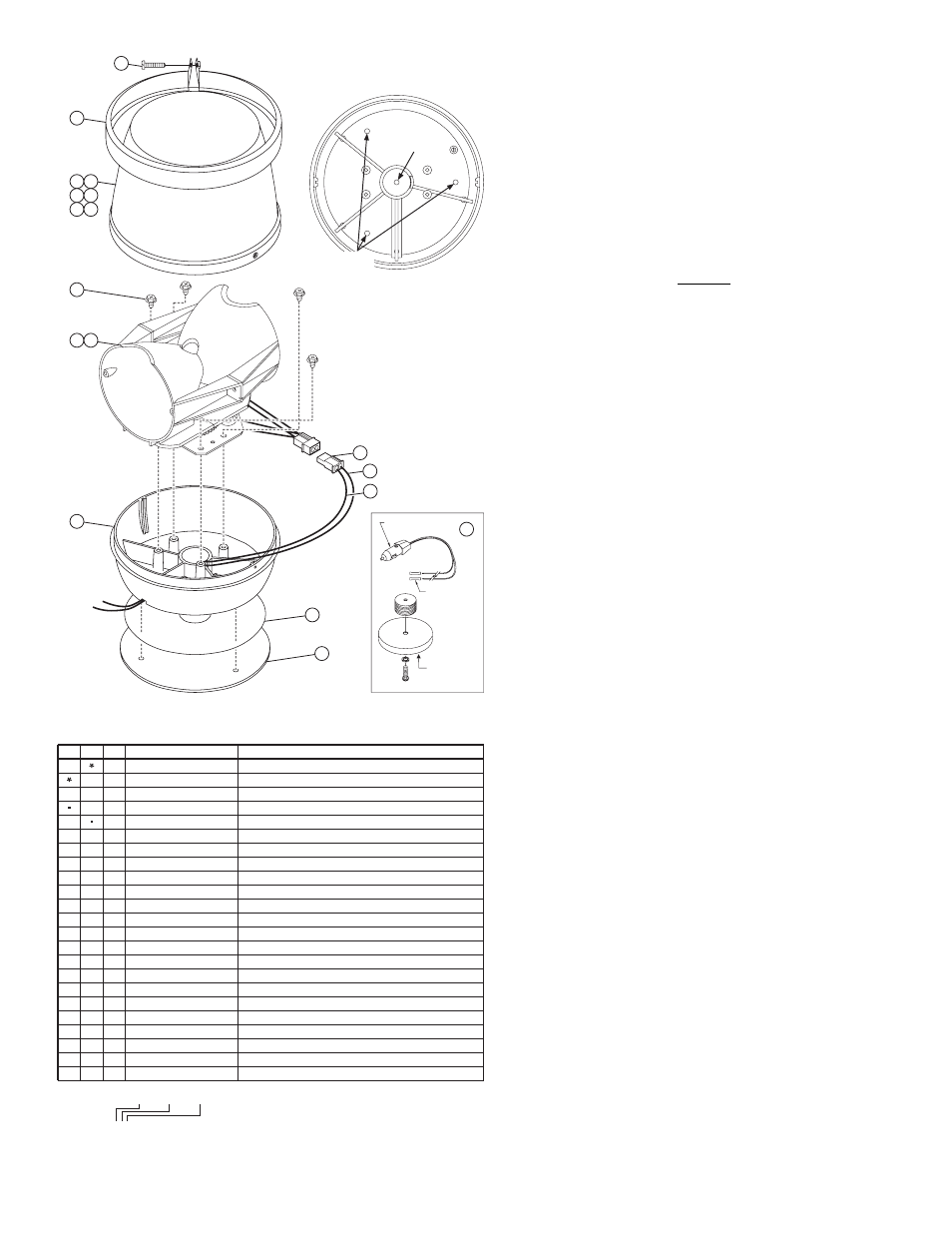
Mounting:
The RB6 Series uses a base that may be mounted one of two
ways. It is designed to be mounted in a normal dome- up
position. If mounted in an inverted position, seal the wire exit
hole and any mounting holes with silicone seal.
WARNING! All customer supplied wires that
connect to the positive terminal of the battery must
be sized to supply at least 125% of the maximum
operating current and FUSED at the battery to carry
that load. DO NOT USE CIRCUIT BREAKERS WITH
THIS PRODUCT!
1” N.P.T. PIPE MOUNT:
1.
Feed the beacon wires through the pipe.
2.
Extend the RED beacon wire to +12VDC and fuse at 7.5
amps (see warning). Extend the BLACK beacon wire to
chassis ground (-). This unit is polarity sensitive!
3.
Screw the strobe beacon onto the pipe, being careful not
to pinch or strain the wires. Hand tighten the unit onto
pipe.
Permanent Surface Mount:
Note: It will be necessary to remove the dome in
order to use this mounting style.
1.
Remove the clamp ring securing the dome to the base
and remove the dome.
2.
Locate the 3 mounting hole indentations on the inside
bottom of the base. Drill openings at these locations sized
to accommodate the sheet metal mounting screws
(customer supplied). Deburr these openings and remove
any shavings.
3.
Using the base as a template, mark the location of the
three mounting holes and wire access hole onto the
mounting surface.
4.
Using an appropriately sized drill bit (based on the
mounting hardware used and the thickness of the
mounting surface), drill the three mounting holes marked
in step 3. The wire access hole should be drilled using a
1/4” drill bit. Deburr all holes and install a rubber grommet
(customer supplied) to protect the wires.
5.
Feed the wires through the wire access hole in the
mounting gasket, and the mounting surface.
6.
Align the mounting holes in the base, gasket, and
mounting surface. Fasten with the three sheet metal
screws.
7.
Extend the RED beacon wire to +12VDC and fuse at 7.5
amps (see warning). Extend the BLACK beacon wire to
chassis ground (-). This unit is polarity sensitive!
8.
A magnet mount or mirror mount kit is available for
purchase separately (see parts list).