Installation, Operation, Mounting holes – Whelen B6MMAAP User Manual
Page 2: Thru hole mounting
Page 2
1. Remove
Dome &
Gasket
1.
1.
MOUNTING SCREWS
(Thru Hole Mounting)
MOUNTING
S U R FA C E
3. Remove
3. beacon's
3. mounting
3. bracket
3. Remove
3. beacon's
3. mounting
3. bracket
MOUNTING
GASKET
2.
Remove
screws
and slide
beacon
out.
2.
3. Remove
beacon's
mounting
bracket
3.
3.
3.
WHITE-VIOLET N/C
W I R I N G
DIAGRAM
WHITE-VIOLET
N/C
GREY
N/C
WHITE-ORANGE
RED
BLACK
This wire is the color of the LED
BLACK
VIOLET
VIOLET
VIOLET
RED
BLACK
VIOLET
WHITE-ORANGE
L360 SERIES
700
SERIES
+12 VDC
Ground
Low Power
Cruise Light
5 AMP
F U S E
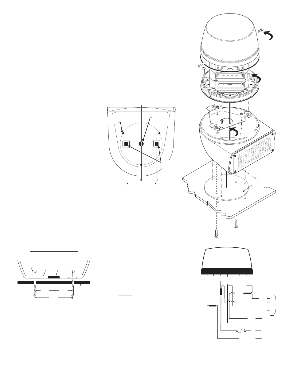
Mounting Holes
TOP VIEW / STANDARD and THRU-HOLE
1-3/4"
3.5"
THRU HOLE
MOUNTING
MOUNTING
HOLES (3)
3/8" DIA
WIRE HOLE
The Model B6MM warning light combines a Super-LED® Beacon with either a 700 Series
Super-LED® lighthead, a Halogen Scenelight a 700 Series LED Scenelight or an M7
lighthead for double warning in one light. It also meets the new standards set by the
NFPA. for the rear upper Zone “C” applications.
Installation:
WARNING! Since this installation will require drilling, it is absolutely necessary
to make sure that no other vehicle components could be damaged by this
process. Check both sides of the mounting surface before starting. If damage is
likely, select a different mounting location.
STANDARD MOUNTING:
1.
Dismantle the unit by first removing the 2 sheet metal screws which hold the lens onto the
beacons base and remove the dome and
gasket.
2.
Remove the three screws that hold the
beacon to the beacon bracket and
separate the beacon from it’s mounting
bracket.
3.
Remove the screws that hold the beacon
bracket to the base and slide the bracket
up and out so you can access the
mounting holes on the bottom of the
base.
4.
Position the base housing onto the
vehicle so that the lower light device is
facing directly rearward, locate the three
mounting holes drilled into the base
housing (See diagram) and mark them off
on the mounting surface of the vehicle.
5.
Remove the unit and position the base
gasket onto the vehicle. Line the gasket
up with the marks you made for the
mounting screws and mark off the center wire access hole using the gasket as a template.
6.
Drill the base mounting holes for the three #10 sheet metal screws and drill the center wire
access hole to 3/8 inch (Grommet wire hole as needed / Customer supplied).
7.
Feed the wires out of the unit, through the mounting gasket and through the access hole
and connect them to your power source. (See wiring)
8.
Attach the base to the vehicle with the 3 sheet metal screws supplied, then reassemble and
test the unit.
THRU HOLE MOUNTING
(Optional): To install the unit
using “Thru Hole Mounting”, on the mounting surface, drill
two holes sized for a ¼” sheet metal screw the distances
shown in the diagram. Be sure the unit is facing the
desired direction that it will face once installed. Insert the
customer supplied screws up through the bottom of the
base and tighten to secure.
WARNING: All customer supplied wires that connect
to the positive terminal of the battery must be sized to
supply at least 125% of the maximum operating
current and FUSED at the battery to carry that load. DO
NOT USE CIRCUIT BREAKERS WITH THIS PRODUCT!
Operation:
Cruise Light:
Apply +12 VDC to the WHITE-ORANGE wire to turn on the cruise light. Remove the voltage from the
WHITE-ORANGE wire to restore normal operation.
Hi/Low Intensity:
Apply +12 VDC to the VIOLET wire to put the beacon into low power. Remove the voltage from the
VIOLET wire to restore normal high power operation.
MOUNTING
SURFACE
F A S T E X
GROMMET
BASE
WIRE
HOLE
1¾"
3½"
1¾"
Thru Hole Mounting
FRONT VIEW / CROSS SECTION