Standard mounting thru hole mounting, Page 2, Installation – Whelen B6TMAA1P User Manual
Page 2: Lo intensity / violet wire, Scan-lock™/ white-violet wire
Page 2
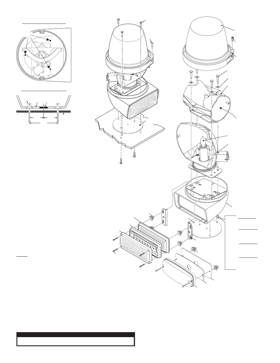
LED MOUNTING
BRACKET
B6R HOUSING
ROTATING MECH
128 FPM 12V
ROTATING MECH
12V 50W
REPLACEMENT
LAMP 12V 50W
3 4 - 0 0 4 1 9 8 7 - 0 6
MOUNTING
GASKET
OPTIC
LENS
700 SERIES
LINEAR TIR
LED FLASHER
GROMMET
#6 INTERNAL TOOTH
LOCK WASHER S.S.
#6 - 32 X 1/2"
PPHMS S.S.
LENS
CLAMP RING
#10 X 3/4"
PPHSMS
TYPE "A"
W I R I N G :
BLACK
WHITE
RED
(-) GROUND
+12V INPUT
+12V INPUT
WHT-VIO Scan-Lock™
BLACK
WHITE
RED
(-) GROUND
+12V INPUT (SPLIT)
+12V INPUT
WHT-VIO Scan-Lock™
BLACK
VIOLET
RED
(-) GROUND
Low Power
+12V INPUT
WHT-VIO Scan-Lock™
BLACK
RED
WHT-VIO
(-) GROUND
+12V INPUT
Scan-Lock™
SPLIT
FLASHER
M7
LINEAR
TIR
FLASHER
or
or
SNAP-IN BULB
(INSIDE) 12V / 60W
3 4 - 0 0 4 1 9 8 7 - 0 7
#6 X 1-1/4"
P P H S M S
M7 SERIES
M7 GASKET
M7/B6 ADAPTOR
GROMMET
or
SignalAlert™
Steady
Steady-Brake
SignalAlert™ 75 Alt.
SignalAlert™ 75 Sim.
CometFlash® 75 Alt.
CometFlash® 75 Sim.
DoubleFlash 150 Alt.
DoubleFlash 150 Sim.
DoubleFlash 75 Alt.
DoubleFlash 75 Sim.
FLASH PATTERNS
SPLIT / 4 WIRE:
SingleFlash 375 Alt.
SingleFlash 375 Sim.
SingleFlash 150 Alt.
SingleFlash 150 Sim.
SingleFlash 75 Alt.
SingleFlash 75 Sim.
ActionFlash™ Alt.
ActionFlash™ Sim.
ModuFlash™ Alt.
ModuFlash™ - Sim.
ActionScan™
SSNF CH-1 Flash
CH-2 Steady
FLASH PATTERNS:
SignalAlert™ 75
SignalAlert™ 150
SingleFlash 375
SingleFlash 150
SingleFlash 75
DoubleFlash 150
DoubleFlash 75
CometFlash® 75
ActionFlash™
ModuFlash™
ComAlert™
ActionScan™
13.
14.
15.
1.
2.
3.
4.
5.
6.
7.
8.
FLASH PATTERNS
SPLIT / 4 WIRE:
9.
10.
11.
12.
13.
14.
15.
16.
17.
18.
19.
20.
FLASH PATTERNS:
1.
2.
3.
4.
5.
6.
7.
8.
9.
10.
11.
12.
MOUNTING
SCREWS
(Standard
mounting)
MOUNTING SCREWS
(Thru Hole Mounting)
#10 X 3/4"
PPHSMS
CLAMP
RING
Standard Mounting
Thru Hole Mounting
TOP VIEW
MOUNTING
HOLES
MOUNTING
SURFACE
F A S T E X
GROMMET
BASE
WIRE
HOLE
1¾"
3½"
1¾"
FRONT VIEW / CROSS SECTION
MOUNTING
GASKET
MOUNTING
S U R FA C E
This warning light combines a rotating beacon and
an LED lighthead for double warning. It also meets new
NFPA standards for rear upper Zone “C” applications.
Installation:
Before installation, read all warnings on the previous page.
1.
Dismantle the light by first removing the screw which
fastens the clamp ring that holds lens on and remove the
lens.
2.
Position the base housing onto the vehicle so that the lower light
device is facing directly rearward, locate the three mounting holes drilled into the base housing (See above) and
mark them off on the mounting surface of the vehicle.
3.
Remove the unit and position the base gasket onto the vehicle. Line the gasket up with the marks you
made for the mounting screws and mark off the center wire access hole.
4.
Drill the base mounting holes for the three #10 sheet metal screws and for the center wire access
hole (Grommet as needed. Customer supplied).
5.
Feed the wires out of the unit, through the mounting gasket and through the access hole and
connect them to your power source. (See wiring)
6.
Attach the base to the vehicle with the 3 sheet metal screws supplied,
then reassemble and test the unit.
OPTIONAL MOUNTING: To install the unit using “Thru Hole
Mounting”, on the mounting surface, drill two holes, sized for a
¼” sheet metal screw following the diagram above. Be sure
that these markings reflect the desired direction that the unit
will face once installed. Insert the customer supplied screws up
through the bottom of the base and tighten to secure.
WARNING!
All customer supplied wires that connect to
the positive terminal of the battery must be sized to supply
at least 125% of the maximum operating current and
FUSED at the battery to carry that load. DO NOT USE
CIRCUIT BREAKERS WITH THIS PRODUCT!
Lo Intensity / Violet Wire:
This feature allows the user
to step the unit down to low power operation for nighttime use.
Apply positive voltage to the VIOLET wire to put the lighthead into low power. Remove voltage
from the VIOLET wire to restore high power operation.
Scan-Lock™/ White-Violet Wire:
Flash pattern selection.
To change flash patterns, first turn the lighthead on:
TO CYCLE THROUGH ALL PATTERNS: Apply +12 volts to the WHITE-VIOLET wire for
less than 1 second and release to cycle forward. Apply +12 volts to the WHITE-VIOLET
wire for more than 1 second and release to cycle backward.
TO SET A PATTERN AS DEFAULT: Allow the desired pattern to run for more than 5
seconds. The lighthead will now display this pattern when active.
TO RESET TO THE FACTORY DEFAULT PATTERN: Turn off power, apply +12 volts to
the WHITE-VIOLET wire, turn power on.
CAUTION! DO NOT LOOK DIRECTLY AT THESE LED’S WHILE THEY ARE ON.
MOMENTARY BLINDNESS AND/OR EYE DAMAGE COULD RESULT!
I M P O R TA N T W A R N I N G !