Assembly and operation: specifications, Mounting: 1 inch (npt) pipe mount, Permanent mount – Whelen 2022LPA User Manual
Page 2: Temporary mount, Mirror mount bracket
Page 2
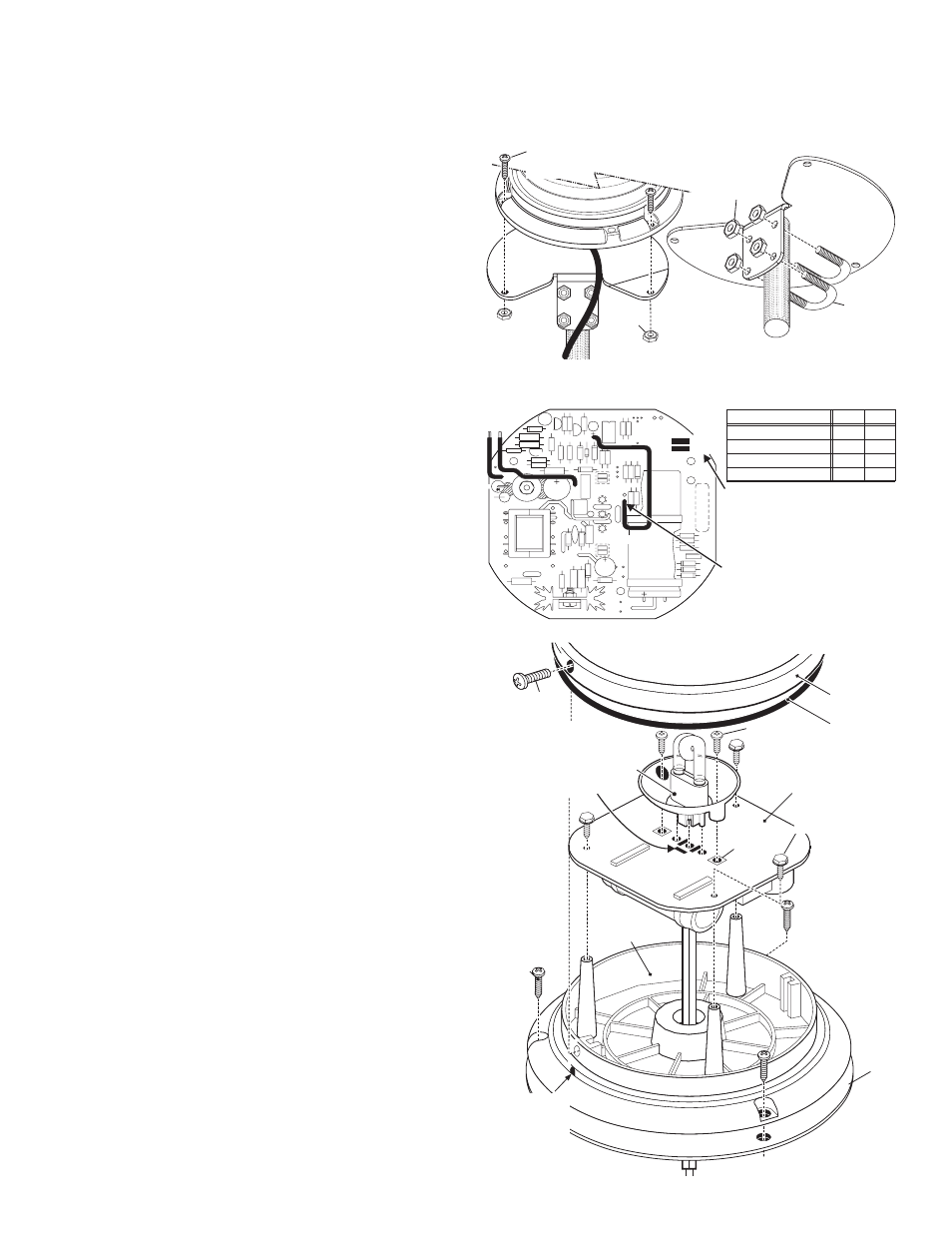
# 4 X 1 / 2 "
PHILLIPS PAN
H E A D S M S
P C B
ASS'Y
OPTIC
DOME
BASE
#10 X 5/8"
PPH SMS
F A S T E X
GROMMET
When inserting the flash
tube assembly into the
strobe power supply
assembly, align the 3
prongs on the flash tube
with the slots in the
power supply.
BASE
SEAL
#6 X 5/8" PAN HD.
THX HD. SCREW
#6 X 5/16" HEX WSHR
HD THD FORM. SCREW
FLASH
T U B E
ASS'Y
I M P O R TA N T:
Keep drain hole
in base facing
rear of vehicle.
H I
/ L O W
G H
P O W E R
If you wish to control Hi/Low Power
externally, cut the VIOLET wire off at this
point and exit with the BLACK and RED
wires. Ground this wire to go to high
power. You may install an SPST switch
(customer supplied).
FLASH PATTERN SELECTION
To achieve any of the 4 flash patterns,
you must either cut-out or leave-in one,
two, both or neither of the two jumpers. If
you do not touch the jumpers the beacon
will default to QuintFlash.
PCB ASSEMBLY (COMPONENT SIDE)
JU1
BLK
JU2
RED
JU6
Q u i n t F l a s h
D o u b l e F l a s h
R a p i d R a n d o m
A c t i o n F l a s h ™
JU1
JU2
IN
IN
CUT
CUT
IN
CUT
IN
CUT
FLASH PATTERNS
FLASH PATTERN SELECTION
HI/LOW POWER CONTROL
O-RING
GASKET
Assembly and Operation:
Specifications:
Input Voltage.................................................................. 12.8 / (25.6) VDC
Input Current..................................................2.5 Amps & 1.25 Amps avg.
Input Power............................................................................... 31.5 Watts
Flashrate: QuintFlash™.......................... 72 QuintFlashes (5) Per Minute
DoubleFlash .......................... 115 Double Flashes Per Minute
RapidRandom......................150-370-150 Flashes Per Minute
ActionFlash ....... 1 QuintFlash & 4 Single Flashes Per Minute
Energy ........................................................8.6 / 2.5 / 2.5 / 2.5 / 2.5 Joules
Output Power............................................................................... 22 Watts
WARNING!The strobe power supply is a high voltage device. Do not
remove flash tubes or dismantle the strobe light head
assembly while in operation. Wait 10 minutes after turning
power off before starting work or trouble shooting.
Mounting:
1 Inch (NPT) Pipe Mount:
1.
Threading for a 1 inch (NPT) pipe mounting is precast in the base.
Feed power cable through pipe and connect cable to beacon.
2.
Screw strobe beacon to threads on the pipe, taking precaution not to
damage the power wires. NOTE: Do not tighten base too hard
onto pipe so as not to damage the threads on the base.
Permanent Mount:
1.
Use the base as a template and mark the three mounting holes onto
the mounting surface. After removing the base, mark in the center
between the 3 mounting holes, the location of the wire access hole.
2.
Drill the mounting holes using a #16 drill bit. Drill a wire access hole
using a 3/8” drill bit. Remove the burrs from the wire access hole so
as not to damage the wires. It is recommended that you install a
rubber grommet to further protect the wires. A gasket will be used
between the beacon base and the mounting surface.
3.
After connecting the beacon to the power cable, feed the wires
through the cable access hole and place the base with the gasket on
the mounting surface, lining up the mounting holes in the base with
the mounting holes in the mounting surface. Secure beacon firmly to
the mounting surface with the #10 X 5/8 Sheet Metal Screws.
Temporary Mount:
Magnetic/suction: Thoroughly clean the proposed mounting surface prior
to mounting. For suction cup mounting, wipe the suction cup clean, place
the beacon onto its mounting surface and apply gentle pressure to ensure
a good seal. The Magnetic/Suction Cups mount the same way as
standard suction cups but are best suited to a flat, steel surface.
Magnetic: Place beacon onto mounting surface and plug into cigar lighter.
WARNING! Beacons equipped with cigar cords are intended for
shortduration, intermittent operation only! Prolonged
operation requires the beacon to be wired to the vehicle.
WARNING! The presence of any temporarily mounted warning light
on the outside of a vehicle in motion is not
recommended and is at the sole discretion and liability
of the user!
WARNING! All customer supplied wires that connect to the positive
terminal of the battery must be sized to supply at least
125% of the maximum operating current and FUSED at
the battery to carry the load. DO NOT USE CIRCUIT
BREAKERS WITH THIS PRODUCT!
DC voltage models are polarity sensitive. If the positive and negative wires
are reversed the unit will not function. The fuse is installed between the
power source and the beacon, in the positive (+) wire (RED) and must be
fused at the battery. A 7.5 AMP Fuse is Recommended for this unit.
1.
Connect the RED wire on the beacon to positive voltage (+). A
customer supplied single pole single throw (SPST) switch may be
used to control the ON/OFF function of the beacon.
2.
Connect the BLACK wire on the beacon to a negative (-) ground.
10-24
ELASTIC
STOP NUT
(QTY 4)
10-24 X 5/8
U-BOLT
(QTY 2)
1. Secure the bracket to the mirror
2 supplied U-Bolts and elastic
1.
or other part of the vehicle using the
stop nuts.
Mirror Mount Bracket
10-24 X 7/8
PPHMS
(QTY 3)
10-24
ELASTIC
STOP NUT
(QTY 3)
2.
using the supplied sheet metal
screws
Secure the Beacon to the bracket
and elastic stop nuts.
2.