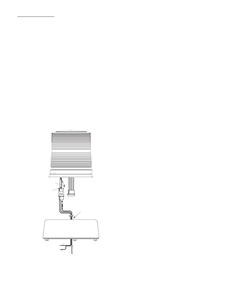
Fig. 5, Jumper options – Whelen 1200DHAP User Manual
Page 4
Page 4
CUT VIOLET
WIRE HERE
PLUG WIRE HERE
ATTACH SOCKET HERE
AND INSERT INTO
SOCKET HOUSING
RED
BLACK
VIOLET
RUN THROUGH
BASE HERE
3
1 2
2
1
3
CUSTOMER OPTIONS
Hi/Low Intensity Option:
1.
Take out the 2 base screws and remove the optic dome
(Fig. 4).
2.
Locate and remove the 2 screws holding the die-cast base
to the aluminum base.
3.
Separate the aluminum base and die-cast base so you
have access to the wiring as shown in Fig. 4 (you will see
that the violet and black wires run together).
4.
Cut the violet wire as indicated in Fig. 5 (at pin 2). Attach
the supplied socket to the end of the violet wire and insert
it into the number 3 space in the socket. NOTE: Cut the
wire close to the socket, so it doesn’t stick out.
5.
Next take the violet wire with the pin attached (included in
the installation kit) and plug it into the connector as shown
in Figure 5.
6.
Run the wires out the bottom of the aluminum base and
reassemble the beacon.
7.
Now, if you ground the violet wire, your light will run at high
intensity, and if you tape off the violet wire, your light will
run at low intensity. You may want to install a two position
switch so you can alternate between the two functions
(see wiring options in Fig. 6).
Flash Pattern Options:
The default flash pattern for the 1200D is CometFlash®. You
may choose from several other patterns by making a few simple
changes.
1.
First remove the optic dome by removing the 2, die-cast
base screws (Fig. 4).
2.
Remove the 2 screws holding the die-cast base to the
aluminum base and separate them, exposing the wires.
3.
Find the input control pigtail assembly in your parts bag,
and plug it in to the extra connector coming out of the die-
cast base.
4.
Run the brown and white wires out through the center of
the base as shown in Figure 4. IMPORTANT: Be sure to
tape off any unused wires.
5.
Reassemble the unit and you are ready to choose your
options.
To Select SingleFlash: Ground the white wire and tape off the
brown wire.
To Select DoubleFlash: Ground the brown wire and tape off
the white wire.
To Select ActionFlash™: Ground both the white and brown
wires.
Jumper Options:
There are several options you can utilize by cutting one, both or
neither of the jumpers located inside the unit (the jumpers are
labeled JU1 and JU2. see Fig. 3).
A. You may run your strobe at either high or low intensity. To
accomplish this you simply leave both jumpers intact and
follow the instructions under “Hi/Low Intensity Option”.
B. Your strobe may also be equiped with the optional
“Photocell function”. This will automatically adjust the
intensity of the strobe light acording to the ambient light
(darkness switches the beacon to low power, while daylight
switches the beacon to high power). To engage this
function you must cut the JU2 jumper and leave the JU1
jumper intact. Then clip the violet wire and tape it off (see
“Hi/Low Intensity Option”). Now the photocell option is
always engaged. If you want to be able to turn this function
on or off manually, you must also attach the violet wire to a
switch that will ground or disconnect it. When you switch to
“ground” the light will always be at high intensity. When you
switch to “disconnect” the light will return to the photocell
function.
C. If you want your strobe to turn on automatically during the
day and off at night, cut the JU1 jumper and leave JU2
jumper intact.
D. If you want your strobe to turn off automatically during the
day and on at night, cut both the JU1 and JU2 jumpers.
IMPORTANT NOTE: Both “C” and “D” are usually used for
remote applications. Once you convert to either of these
functions you will not be able use the light any other way.
Fig. 5