Fig. 1, Wiring, Mounting – Whelen L21HAP User Manual
Page 2: Operation: sync, Hi/low power: photocell, Programming / scan-lock™ / white-violet
Page 2
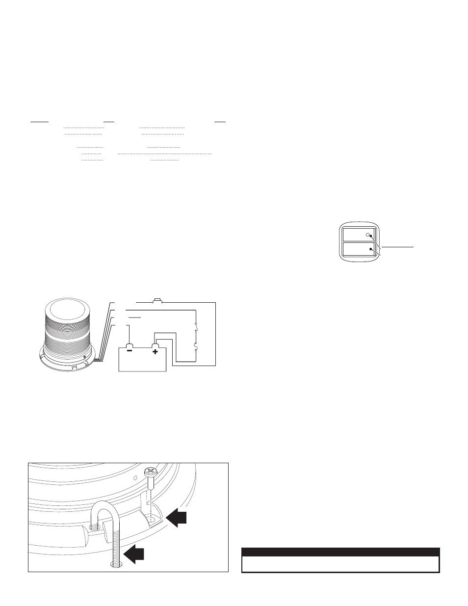
S P S T
switch
Momentary switch
3 AMP
F u s e
Connect to SYNC wire of
other beacon or Cut & cap
GREY wire
RED
BLK
WHT/VIO
GREY
BATTERY
PERMANENT
MOUNT
"J" HOOK
MOUNT
Fig. 1
L21: This Beacon has fully encapsulated electronics that are impervious
to damage from moisture and vibration. Some units feature an automatic
photocell High Power override. This beacon also features Scan-Lock™
which allows you to choose between 25 available flash patterns. You have
6 available mounting options (not all included with beacon): mirror mount,
permanent mount, pipe mount, J-hook mount, magnetic mount and
Vacuum mount. (Magnetic and Vacuum mount do not include SYNC.) All
models are SAE certified.
IMPORTANT! All beacons in this manual should be fused at 3 AMPS.
IMPORTANT! Always be sure the drain hole (located on the bottom of
the base) is facing the rear of the vehicle after mounting.
WARNING: All customer supplied wires that connect to the positive
terminal of the battery must be sized to supply at least 125% of the
maximum operating current and FUSED at the battery to carry the
load. DO NOT USE CIRCUIT BREAKERS WITH THIS PRODUCT!
Wiring:
Listed below are the wire designations for the L21 beacon. To extend the
beacons wires, use the wire gauge indicated.
WIRE COLOR . . . . . . . . . . WIRE GAUGE . . . . . . . . . . . . . . .FUNCTION
RED. . . . . . . . . . . . . . . . . . 18 AWG . . . . . . . . . . . . . . . . . . . . . . .Positive
BLACK . . . . . . . . . . . . . . . 18 AWG . . . . . . . . . . . . . . . . . . . . . . . Ground
GREY . . . . . . . . . . . . . . . . 18 or 22 AWG . . . . . . . . . . . . . . . . . . . . SYNC
WHITE-VIOLET. . . . . . . . . 18 or 22 AWG . . . . . . . . . . . . . . .Scan-Lock™
Mounting:
“J” HOOK MOUNT:
This beacon is equipped to handle the “J” hook mount available on some
beacons. Be sure to use the correct “J” hook mounting holes (Fig. 1).
PERMANENT MOUNT:
1.
Use the base as a template and mark the three mounting holes off
onto the mounting surface. Remove base. In the center between the
three mounting holes, mark the location of the wire access hole.
2.
Drill the mounting holes with a #16 drill bit. Drill the wire access hole
using a 3/8” drill bit. Remove any burrs from the wire access hole and
It is also recommended that you install a rubber grommet (customer
supplied) into the wire hole to protect the wires.
3.
A base seal is used between the beacon base and mounting surface.
4.
Feed the wires first through the base seal and then through the cable
access hole and place the base (with seal) on the mounting surface
(while lining up the mounting holes in the base with the mounting
holes you drilled into the mounting surface). Secure the beacon
firmly to the mounting surface with the supplied mounting screws.
1 INCH (NPT) PIPE MOUNT:
Threading for a 1 inch (NPT) pipe mounting is precast in the base.
1.
Feed power cable through the 1 inch pipe and connect the cable to
the wires of the beacon.
2.
Screw the beacon into the threads on the 1” pipe, taking precaution
not to damage the connected power wires. Do not tighten base too
hard as not to damage threads on base.
TEMPORARY MOUNT:
IMPORTANT WARNING: The use
of any magnetically mounted
warning device on the outside
of a vehicle in motion is not
recommended and is at the sole risk and responsibility of the user.
Magnetic/suction: Thoroughly clean the proposed mounting surface prior
to mounting. For suction cup mounting, wipe the suction cup clean, place
the beacon onto its mounting surface and apply gentle pressure to ensure
a good seal has been achieved. Magnetic/Suction Cups mount the same
as standard suction cups but are best suited to a flat, steel surface.
Magnetic: Place the beacon onto the mounting surface and plug it into the
vehicle cigar lighter. Magnetic mount models do not offer SYNC.
Operation: SYNC:
To SYNC two beacons, configure both beacons to display the same
Phase 1 (Simultaneous) pattern. Turn the power off and connect the
GREY wire from each beacon together. When the beacons are activated
their patterns will be synchronized. To configure two beacons to alternate
their patterns, advance the pattern of either beacon to Phase 2
(Alternating) of the current pattern. (Not available on cigar plug models)
Hi/Low Power: Photocell
If this beacon is equipped with photocell Hi-Low, the beacon will
automatically step down to low power at night. This feature is optional.
Programming / Scan-Lock™ / White-Violet:
To cycle forward through all patterns: With the beacon switched on,
apply Positive (+) voltage to the WHT-VIO wire for less than 1 second and
release. To cycle backward through all patterns: Apply Positive (+)
voltage to the WHT-VIO wire for more than 1 second and release.
To set a pattern as default: When the desired pattern is displayed, allow
it to run for more than 5 seconds. The beacon will now display this pattern
when activated.
To reset to the factory default pattern: Turn off power. Now, while
applying Positive (+) voltage to the WHITE-VIOLET wire, turn power on.
NOTE: Cigar cord models have a momentary switch on the plug to
control Scan-Lock™ as well as an On/Off switch.
NOTE: The cigar cord adaptor
is equipped with an 8 Amp fuse.
Use a replacement fuse with an
identical value.
Switch Functions:
SW1 = ON/OFF
SW2 = Scan-Lock™ / Momentary
(12 volt model only)
Electrical Specifications
0.75 amps
Peak:
Peak: 1.5 amps
SignalAlert™ / Sim.
ScanLock
Current
™
ScanLock™ CTRL
12.8 VDC +/- 20%
25.6 VDC +/- 20%
10ma
0.30 amps
Avg:
Input Current
Input Voltage
Power
12.8 VDC ± 20%
12V
25.6 VDC ± 20%
24V
20ma
Avg: 0.60 amps
Default Flash Pattern
SignalAlert™ / Sim.
CAUTION! DO NOT LOOK DIRECTLY AT THESE LEDS WHILE THEY ARE ON.
MOMENTARY BLINDNESS AND/OR EYE DAMAGE COULD RESULT!
IMPORTANT WARNING!