Mounting dimensions permanent mount – Whelen L10HAP User Manual
Page 2
Page 2
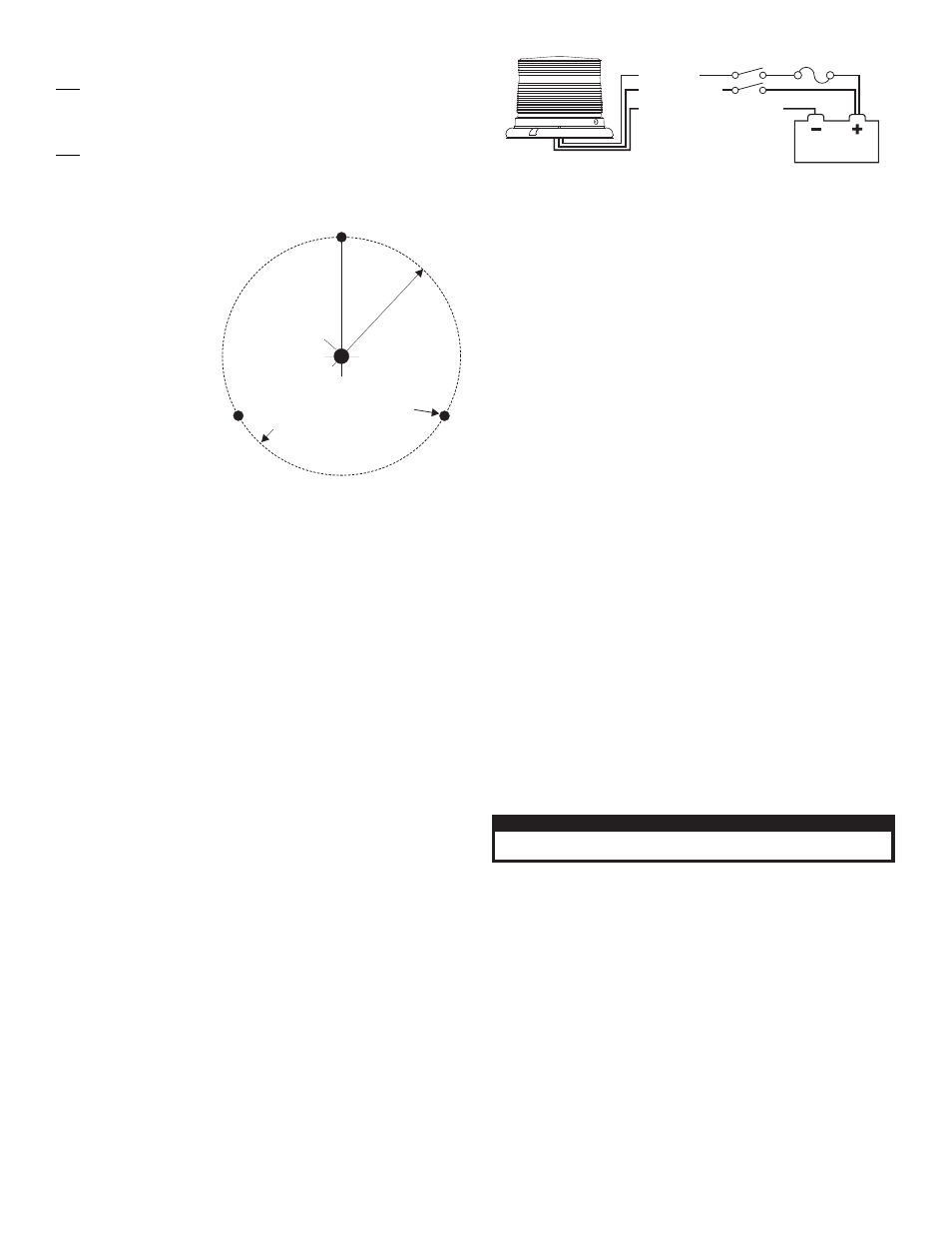
WIRING DIAGRAM
ALL FUSES AND SWITCHES
ARE CUSTOMER SUPPLIED
BLK (12V) or BLK/WHT (24V) - GROUND
WHT/VIO - SCANLOCK
RED - POSITIVE
SPST SWITCH
SPST SWITCH
3 AMP FUSE
BATTERY
MTG. HOLES FOR
#10 SCREWS (3)
3/8" DIA. WIRE
ACCESS HOLE
5.937"
DIA.
B.C.
MOUNTING DIMENSIONS
PERMANENT MOUNT
Specifications:
12V
Input Voltage. . . . . . . . . . . . . . . . . . . . . . . . . . . . . 12.8 VDC +/- 20%
Input Current / Peak . . . . . . . . . . . . . . . . . . . . . . . . . . . . . . . . 1 AMP
Input Current / Avg. . . . . . . . . . . . . . . . . . . . . . . . . . . . . . .0.4 AMPS
24V
Input Voltage. . . . . . . . . . . . . . . . . . . . . . . . . . . . . 25.6 VDC +/- 20%
Input Current / Peak . . . . . . . . . . . . . . . . . . . . . . . . . . . . . .0.5 AMPS
Input Current / Avg. . . . . . . . . . . . . . . . . . . . . . . . . . . . . . .0.2 AMPS
Permanent Mount:
1.
Using the base as a
template, mark the 3
mounting holes onto
the mounting
surface. Remove
the base and mark
the location of the
wire access hole,
centered between
the 3 mounting
holes.
2.
Drill the mounting
holes using a drill bit
sized for a #10
screw. Drill a wire
access hole using a
3/8” drill bit. Remove
the burrs from the
wire access hole so as not to damage the wires. It is
recommended that a rubber grommet be installed to further
protect the wires. A gasket will be used between the beacon
base and the mounting surface.
3.
After connecting the beacon to the power cable, feed the wires
through the cable access hole and place the base and gasket on
the mounting surface. Align the mounting holes in the base with
the mounting holes in the mounting surface. Secure beacon
firmly to the mounting surface using the #10 X 5/8 Sheet Metal
Screws provided.
1 Inch (NPT) Pipe Mount:
Threading for a 1” NPT pipe mounting is precast into the base. Feed
the power cable through the 1 “ pipe and connect to wires of beacon.
Screw the beacon to the threads on the pipe, taking precaution not to
damage the power wires. NOTE: Do not tighten the base too hard
so as not to damage the threads.
Temporary Mount (Magnetic, Suction Cup, etc.)
With the magnetic or magnetic/suction cup mounting options
you will be able to mount your beacon so that you can remove it
if necessary and avoid drilling.
Magnetic/suction: Thoroughly clean the proposed mounting surface
prior to mounting. For suction cup mounting, wipe the suction cup
clean, place the beacon onto its mounting surface and apply gentle
pressure to ensure a good seal has been achieved. The Magnetic/
Suction Cups mount the same way as standard suction cups but are
best suited to a flat, steel surface.
Magnetic: Place the beacon onto the mounting surface and
plug it into the vehicle cigar lighter.
Wiring:
WARNING! All customer supplied wires that connect to the
positive terminal of the battery must be sized to supply at least
125% of the maximum operating current and FUSED at the
battery to carry the load. DO NOT USE CIRCUIT BREAKERS
WITH THIS PRODUCT!
This product is polarity sensitive. If the positive and negative wires are
reversed the unit will not function. Fuse the positive (RED) wire @ 3
Amps at the battery.
1.
Connect the RED wire to positive voltage (+VBAT). A customer
supplied single pole/single throw (SPST) switch may be used to
control the ON/OFF function of the beacon.
2.
Connect the BLK or BLK/WHT wire to chassis ground.
Operation:
Scan-Lock™ (White/Violet):
To use Scan-Lock™, the beacon must be turned on:
TO CHANGE PATTERNS: To cycle forward to the next available pat-
tern apply +VBAT to the WHT/VIO wire for less than 1 second and
release. To cycle back to the previous pattern apply +VBAT to the
WHT/VIO wire for more than 1 second and release.
TO CHANGE THE DEFAULT PATTERN: When the desired pattern is
displayed, allow it to run for more than 5 seconds. The beacon will
now display this pattern when initially activated.
TO RESTORE THE FACTORY DEFAULT PATTERN: With the power
to the beacon off, apply +VBAT to the WHT/VIO wire. Turn power to
the beacon on. The factory default pattern should now be displayed.
A normally open momentary switch can be used to control Scan-
Lock™ operation.
Flash Patterns:
IMPORTANT: It is the responsibility of the installation technician
to make sure that the installation and operation of this product
will not interfere with or compromise the operation or efficiency
of any vehicle equipment! Permanent mounting of this product
will require drilling. It is absolutely necessary to make sure that
no other vehicle components could be damaged by this process.
Check both sides of the mounting surface before starting. If
damage is likely, select a different mounting location.
1.
SignalAlert™ 75
2.
CometFlash® 75
3.
DoubleFlash 75
4.
SingleFlash 75
5.
ComAlert™ 75
6.
LongBurst™ 75
7.
PingPong™ 75
8.
SingleFlash 60
9.
SingleFlash 90
10. SingleFlash 120
11. SingleFlash 300
12. DoubleFlash 150
13. ComAlert™ 150
14. ActionFlash™ 50
15. ActionFlash 150
16. ModuFlash™
17. ActionScan™
18. Steady
CAUTION! DO NOT LOOK DIRECTLY AT THESE LED’S WHILE THEY ARE ON.
MOMENTARY BLINDNESS AND/OR EYE DAMAGE COULD RESULT!
I M P O R TA N T W A R N I N G !