Operation, Mounting, Wire function – Whelen L51AP User Manual
Page 2: Page 2, Important warning, Permanent mount, Magnetic mount
Page 2
CAUTION! DO NOT LOOK DIRECTLY AT THESE LEDS WHILE THEY ARE ON.
MOMENTARY BLINDNESS AND/OR EYE DAMAGE COULD RESULT!
IMPORTANT WARNING!
Specifications
L51
L52
12V
24V
12V
24V
Input Voltage
-
Input Current
-
12.8V
25.6V
12.8V
25.6V
Peak
1.50A
0.75A
0.75A
.375A
Avg.
0.60A
0.30A
0.30A
0.15A
1 2
11
8
10
6
7
9
5
3
4
Model L51
shown.
12
RED - (+VBAT)
BLACK - (GROUND)
GREY - (SYNC)
WHT/VIO - (ScanLock)
Patterns (SYNC):
1.
2.
™
3.
4.
5.
75
6.
75
7.
Sing
8.
Sing
9.
ComAlert™ 75
10. ComAlert™ 75 Phase 2
11. LongBurst™ 75
12. LongBurst™ 75
SignalAlert™ 75 Phase 1
SignalAlert
75 Phase 2
CometFlash® 75 Phase 1
CometFlash® 75 Phase 2
DoubleFlash
Phase 1
DoubleFlash
Phase 2
leFlash 75 Phase 1
leFlash 75 Phase 2
Phase 1
Phase 1
Phase 2
13. PingPong™ 75
14. PingPong™ 75 Phase 2
. SingleFlash 90
17. SingleFlash 120
18. SingleFlash 300
19. ComAlert™ 150
20. ActionFlash™ 1
21.
Flash™ 2
22. ModuFlash™
23. ActionScan™
Non-SYNC
Phase 1
(
)
15. SingleFlash 60
16
Action
Patterns
1
1
ITEM
PART NUMBER
DESCRIPTION
LED BEACON MODEL L51
LED BEACON MODEL L51
LED BEACON MODEL L52
LED BEACON MODEL L52
L51 BEACON SUB ASSEMBLY (12V)
L51 BEACON SUB ASSEMBLY (12V)
L52 BEACON SUB ASSEMBLY (12V)
L52 BEACON SUB ASSEMBLY (12V)
L51 BEACON SUB ASSEMBLY (24V)
L52 BEACON SUB ASSEMBLY (24V)
O-RING
LENS, AMBER
LENS, CLEAR
GASKET
SCREW, #10 x 1" PPHSMS
GROMMET, 3/8"
0 1 - 0 6 8 4 9 7 2 _ _ P
0 1 - 0 6 8 4 9 7 2 1 _ M
0 1 - 0 6 8 4 9 7 3 _ _ P
0 1 - 0 6 8 4 9 7 3 1 _ M
0 1 - 0 2 6 A 5 3 1111
0 1 - 0 2 6 B 1 0 1111
0 1 - 0 2 6 B 1 0 1 2 11
0 1 - 0 2 6 A 5 3 11 3 2
0 1 - 0 2 6 A 5 3 1 2 11
0 1 - 0 2 6 A 5 3 1 2 3 2
3 8 - 0 4 1 7 0 4 4 - 0 0
6 8 - 1 9 8 3 5 0 7 - 1 0
6 8 - 1 9 8 3 5 0 7 - 3 0
3 8 - 0 2 2 2 7 7 7 - 0 0
2 1 - 11 0 9 1 2 0 2 - 0
QTY
QTY
QTY
QTY
A/R
A/R
A/R
A/R
A/R
A/R
A/R
1
1
3
3
1
1
1
1
3
3
1
1
1
1
A/R
A/R
A/R
*
*
*
*
A/R
A/R
A/R
A/R
2
3
4
5
6
7
8
9
10
11
12
1
Remember....
Phase 1
alternates with Phase 2
always
Beacon 1
Phase 1
Beacon 1
Phase 1
Beacon 2
Phase 1
Beacon 2
Phase 2
NOTE: This cigar cord uses an
8 Amp fuse. Use replacement
fuses with identical values.
Switch Functions:
SW1 = ON/OFF
SW2 = Scan-Lock™
(12V models only)
MAGNETIC MOUNT
WARNING!
All customer supplied wires that connect to the positive terminal
of the battery must be sized to supply at least 125% of the maximum operating
current and FUSED at the battery to carry that load. DO NOT USE CIRCUIT
BREAKERS WITH THIS PRODUCT
Operation:
Scan-Lock™ - Activate the RED wire to turn on the beacon. Activate the WHT/VIO
wire for less than 1 second and release to cycle forward through patterns. Activating
the WHT/VIO wire for more than 1 second will cause the lighthead to cycle backward
through patterns. When the desired pattern is displayed, allow it to run for more than
5 seconds. The lighthead will now display this pattern when active. To reset to the
factory default pattern, turn off power, activate the WHT/VIO wire, then turn power
back on. See below for pattern information.
Sync - To sync two lightheads, configure both lightheads to display the same Phase
1 pattern. With the power off, connect the GREY wires from each lighthead together.
When the lightheads are activated, their patterns will be synchronized. To configure
the two lightheads to alternate their patterns, advance the pattern of either lighthead
to the Phase 2 mode of the current pattern.
The following example will demonstrate how to use the SYNC feature with more than
2 lightheads. In this sample system, there are 4 lightheads. 2 are mounted on the
rear, driver side of the vehicle and 2 mounted on the rear, passenger side of the
vehicle.
With all the wiring complete, turn on the 4 lightheads. As shipped from the factory, all
the lightheads will simultaneously display the same pattern (SignalAlert 75 Phase 1).
To configure, for example, the passenger side lightheads to alternate with the driver
side lightheads, change the flash patterns for either the passenger or driver side
lightheads to Phase 2 mode of the same pattern. Do not SYNC more than 8 (eight)
beacons!
IMPORTANT: It is the responsibility of the installation technician to make sure
that the installation and operation of this product will not interfere with or
compromise the operation or efficiency of any vehicle equipment! Before
returning the vehicle to active service, visually confirm the proper operation of
this product, as well as all vehicle components/equipment.
Mounting:
Permanent Mount:
CAUTION: Permanent mounting of this
product will require drilling. It is
absolutely necessary to make sure that
no other vehicle components could be
damaged by this process. Check both
sides of the mounting surface before
starting. If damage is likely, select a
different mounting location
.
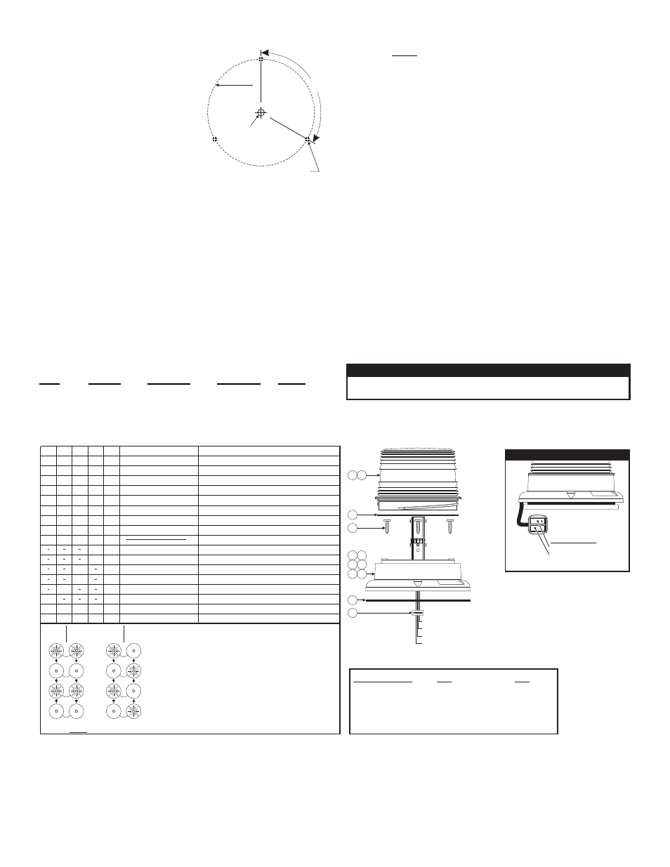
1. Use the base as a template and mark the
three mounting holes off onto the mounting
surface. Remove base. In the center
between the three mounting holes, mark the
location of the wire access hole.
2. Drill mounting holes into the mounting surface with a #16 drill bit. Drill the wire
access hole using a 3/8” drill bit. Remove any burrs from the wire access hole and
install a rubber grommet (customer supplied) into the wire hole to protect the
wires.
3. The base seal goes between the beacon base and the mounting surface.
4. Feed the wires first through the base seal and then through the cable access hole.
Place the base (with seal) on the mounting surface and align the beacon mounting
holes with the mounting holes drilled in step 2. Secure the beacon firmly to the
mounting surface using the supplied #10 mounting screws.
Magnetic Mount
(optional)
:
WARNING: The use of any magnetically mounted warning device on the
outside of a vehicle in motion is not recomended and is at the sole risk and
responsibility of the user.
Magnetic: Place the beacon onto a flat, metal surface surface and plug it into the
vehicle cigar lighter.
Wire Function:
Color
Function
Connect to:
Switch Type
Fuse @
RED . . . . . . . Power. . . . . . . . . +VBAT . . . . . . . . . . SP/ST . . . . . . . . . .3 Amp
BLK . . . . . . . . Ground. . . . . . . . Chassis Ground . . . n/a . . . . . . . . . . . . . . . N/A
GRY . . . . . . . Sync. . . . . . . . . . See text . . . . . . . . . N/A. . . . . . . . . . . . . . . N/A
WHT/VIO. . . . Scan-Lock™ . . . +VBAT . . . . . . . . . . MOM (N.Open) . . .1 Amp
4.626"dia.
bolt circle
3/8" dia. wire
access hole
Mounting holes
(3) for #10 screws
120°