Mirror mount bracket, Mounting, Permanent mount – Whelen L53AP User Manual
Page 2: Magnetic mount, Scan-lock, Page 2
Page 2
1.
Secure the Beacon to the bracket using the supplied sheet metal screws and
elastic stop nuts.
1.
2.
Secure the bracket to the mirror
U-Bolts and elastic
or other part of the vehicle using the two
supplied
stop nuts.
2.
Mirror Mount Bracket
10-24 X 7/8 PPHMS (QTY 3)
10-24 ELASTIC
STOP NUT (QTY 3)
10-24 X 5/8
U-BOLT (QTY 2)
10-24 ELASTIC
STOP NUT (QTY 4)
Ribbed
(-)
Smooth
(+)
On/Off
Switch
Cigar Cord with
on/off switch &
internal 8A fuse
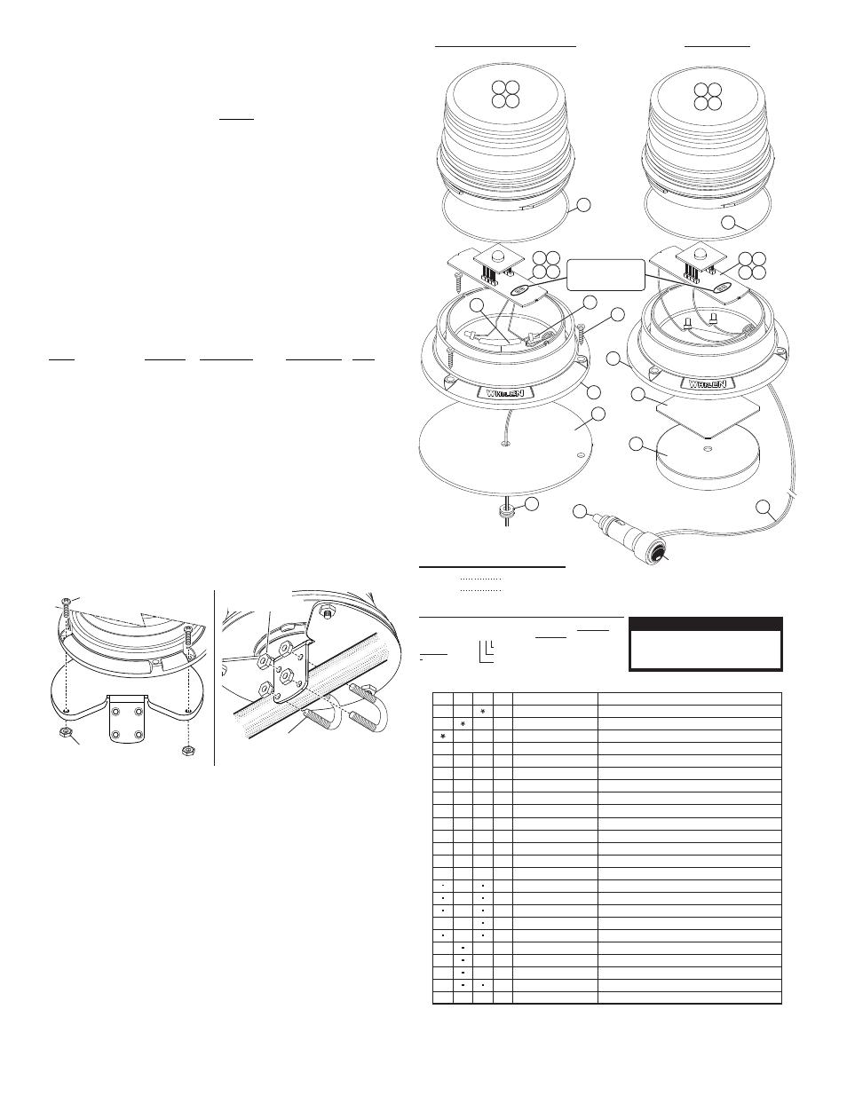
MAG. MOUNT
PERM. MOUNT 12 or 24 VOLT
10
11
11
12
14
16
13
15
5
5
1 2
3 4
M = MAGNETIC
P = PERMANENT
MOUNTING
R = RED
C = CLEAR
B = BLUE
A = AMBER
LED/DOME
C O L O R
VOLTAGE
COLOR
MOUNTING
0 1 - 0 6 8 5 9 6 0 - _ _ _
PART NUMBER KEY :
Voltage
Current
Default Pattern
L53 Series Class III LED Beacon
12 or 24 VDC
400mA (max.) / 160mA (avg.)
SignalAlert™75
15
1 2
3 4
6
6
7
7
8
8
9
9
14
1 0 - 0 3 2 3 2 8 3 - 0 3
0 1 - 0 2 4 3 2 6 0 - 0 0
0 1 - 0 6 8 5 9 6 0 2 _ _ P
0 2 - 0 1 6 9 8 1 2 - 5 0
0 2 - 0 1 6 9 8 1 2 - 3 0
0 2 - 0 1 6 9 8 1 2 - 2 0
0 1 - 0 6 8 5 9 6 0 - _ _ P
0 1 - 0 6 8 5 9 6 0 - _ _ M
11 - 3 8 3 5 0 6 - 0 0 1
0 2 - 0 1 6 9 8 1 2 - 1 0
3 8 - 0 4 1 7 0 4 4 - 0 0
6 5 - 0 0 1 0 1 9 2 - 0 0
6 8 - 1 9 8 3 5 0 7 - 1 0
6 6 - 0 4 2 1 2 7 3 - 0 0
6 9 - 1 3 1 7 2 4 1 - 0 0
2 5 - 0 9 1 0 2 2 3 - 0 3
1 5 - 1 0 1 4 1 6 - 1 6 0
2 1 - 11 0 9 1 2 0 2 - 0
3 8 - 0 2 2 2 7 7 7 - 0 0
1 0 - 0 3 2 2 7 8 3 - 0 2
6 8 - 1 9 8 3 5 0 7 - 2 0
6 8 - 1 9 8 3 5 0 7 - 3 0
6 8 - 1 9 8 3 5 0 7 - 5 0
1 0 - 0 5 2 6 1 2 8 - _ _
AR
AR
AR
AR
AR
AR
1
1
1
1
1
1
AR
AR
AR
AR
AR
AR
AR
1
1
AR
AR
1
AR
AR
1
1
1
1
1
AR
1
3
3
1
1
1
2
2
1
1
1
1
1
1
1
1
1
CLASS 3 BEACON L53 SERIES / PERM MNT / 24V
CLASS 3 BEACON L53 SERIES / PERM MNT / 12V
CLASS 3 BEACON L53 SERIES / MAG MNT / 12V
PCB ASSY BALLAST CLASS 3 LED BEACON RED
/
PCB ASSY BALLAST CLASS 3 LED BEACON WHITE
/
PCB ASSY BALLAST CLASS 3 LED BEACON BLUE
/
PCB ASSY BALLAST CLASS 3 LED BEACON AMBER
/
CORD CIG PLUG STRT 10' 18GA ON/OFF SWITCH 8A FUSE
/
.
.
BASE / MID-SIZE BEACON WHELEN LOGO
/
LENS MID-SIZE BEACON AMBER
/
/
LABEL WHELEN MODEL VOLTAGE L53 SERIES
/
LENS MID-SIZE BEACON BLUE
/
/
LENS MID-SIZE BEACON CLEAR
/
/
LENS MID-SIZE BEACON RED
/
/
O-RING
LABEL / MODEL L53 SERIES
ASSY 24V TO 12V CONVERTER
MAGNET 90# PULL
/
DOUBLE-SIDED TAPE
LABEL AIRBAG & MAG MOUNT WARNING
/
#10 PPHSMS 1"
BUTT TERMINAL
3/8" GROMMET
GASKET
2
3
ITEM
PART NUMBER
DESCRIPTION
QTY QTY QTY
11
12
13
14
15
16
17
18
19
20
4
5
6
7
8
9
10
1
21
Solder Pads
See "Scan-Lock™"
for operation
20
CAUTION! DO NOT LOOK DIRECTLY AT
THESE LED’S WHILE THEY ARE ON.
MOMENTARY BLINDNESS AND/OR EYE
DAMAGE COULD RESULT!
IMPORTANT WARNING!
VOLTAGE
2 = 24V
= 12 V
Flash Patterns:
1. SignalAlert™ 75
2. SignalAlert™ 150
3. SingleFlash 375
4. SingleFlash 150
5. SingleFlash 75
11. ComAlert™
12. ActionScan™
13. SignalAlert™ Steady
14. Steady (high intensity)
15. Steady (low intensity)
6. DoubleFlash 150
7. DoubleFlash 75
8. CometFlash®
9. ActionFlash™
1 0 . M o d u F l a s h ™
0
Mounting:
The L53 beacon is available in Permanent mount, Magnetic mount and mirror
mount. The L53 beacon is designed to be mounted in a normal dome-up position.
WARNING! All customer supplied wires that connect to the positive
terminal of the battery must be sized to supply at least 125% of the
maximum operating current and FUSED at the battery to carry that
load. DO NOT USE CIRCUIT BREAKERS WITH THIS PRODUCT!
Permanent mount:
1.
Position the beacon in its mounting location (refer to warnings on page 1).
2.
Locate the 3 mounting holes on the bottom of the base. Using the base as a
template, mark the location of the these holes onto the mounting surface.
Remove the beacon and make a mark in the center of the beacons mounted
position for a wire passage hole.
3.
Using a #16 drill bit, drill the three mounting holes marked in the previous
step. The wire access hole should be drilled using a 3/8” drill bit. Deburr all
holes and install the rubber grommet (supplied) to protect the wires.
4.
Position the mounting gasket onto the mounting surface so that the gasket
holes are aligned with the mounting holes.
5.
Feed the wires through the wire access hole in the mounting surface.
6.
Align base with mounting holes and secure with #10 sheet metal screws.
Wire Function:
Color
Function
Connect to:
Switch Type Fuse
@
COLOR of LED
*
. . . . Power . . . . +12 or 24 VDC . . . SP/ST . . . . . . . 1 Amp
BLACK . . . . . . . . . . . Ground . . . Chassis Ground . . N/A . . . . . . . . . . . .N/A
*
Wire will be the same color the LED in the beacon is (RED, AMBER, BLUE or WHITE).
Magnetic Mount:
Place the beacon on any flat metal surface and plug the cigar cord into the
vehicles cigar lighter. The beacon is controlled with the On/Off cigar cord switch.
IMPORTANT! The use of any magnetically mounted warning beacon on
the outside of a vehicle while in motion is not recommended and is at
the sole discretion and responsibility of the user.
Scan-Lock™
Unscrew and remove the lens from the base. With the beacon active, to cycle
forward through the patterns short the two solder pads (shown below) for less
than 1 second. More than a second causes the beacon to cycle backwards
through the patterns. To reset to the factory default pattern turn off the beacon,
and with the solder pads shorted out, activate the beacon.
IMPORTANT! It is the responsibility of the installation technician to
make sure that the installation and operation of this product will not
interfere with or compromise the operation or efficiency of any vehicle
equipment! Before returning the vehicle to active service, visually
confirm the proper operation of this product, as well as all vehicle
components/equipment.