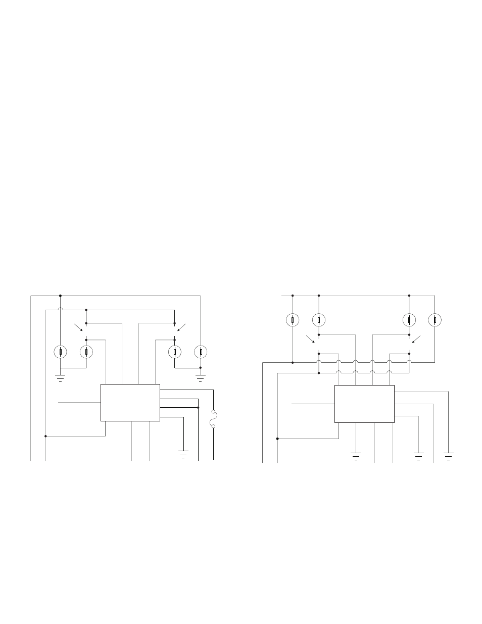
Uhf2150a, Negative-side switched headlights, Positive-side switched headlights – Whelen UHF2150A User Manual
Page 2
Page 2
CUT
CUT
LO
PARKING
LIGHTS
(GROUND
ACTIVE)
LOW
BEAM
SWITCH
(-)
HIGH
BEAM
SWITCH
(-)
GROUND
GROUND
GROUND
WHT / VIO
SCAN-LOCK™
LO
HI
HI
+12VDC
Negative-side Switched Headlights
DRIVER
PASS
UHF2150A
X
X
WHT/BLK
RED
WHT / YEL
YEL
WHT / BLU
BLU
ORN
BLK
WHT
BRN
WHT
/BRN
CONTROL
+12VDC
PARKING
LIGHTS
(+12VDC
ACTIVE)
X
X
PARKING
LIGHTS
(GROUND
ACTIVE)
LOW
BEAM
SWITCH
(+)
HIGH
BEAM
SWITCH
(+)
GROUND
WHT
WHT / VIO
SCAN-LOCK™
HI
HI
LO
LO
DRIVER
BLU
CUT
CUT
YEL
WHT / BLU
Positive-side Switched Headlights
WHT / YEL
PASS
UHF2150A
BLACK
WHT/BLK
ORANGE
RED
WHT
/BRN
BRN
CONTROL
+12VDC
BA
TTER
Y
+12VDC
PARKING
LIGHTS
(+12VDC
ACTIVE)
15
Amp
Fuse
(Customer
Supplied)
1.
Mount the flasher in the engine compartment near the
headlights.
2.
GROUND - Connect the BLACK wire to the vehicle’s chassis
ground.
3.
NIGHT CUTOUT - BROWN - Connect this wire to the parking
light or low beam circuit to disable the flasher when
headlights are on. This is to prevent both filament in a dual
filament bulb from being on simultaneously (or if required in
your jurisdiction).
4.
High Beam Override - Connect the WHITE wire to the
vehicle’s chassis.
Splice the WHITE/BLACK wire into the circuit that the
WHITE/BLUE wire is to be connected to in step 5.
5.
Driver Side Lamp - Locate the wire that connects the driver
side high beam lamp to the headlight dimmer switch. Cut this
wire at a point 3 inches away from the lamp. Connect the
BLUE wire to the wire that connects to the high beam lamp.
Connect the WHITE/BLUE wire to the wire that connects to
the headlight dimmer switch.
6.
Passenger Side Lamp - Locate the wire that connects the
passenger side high beam lamp to the headlight dimmer
switch. Cut this wire at a point 3 inches away from the lamp.
Connect the YELLOW wire to the wire that connects to the
high beam lamp. Connect the WHITE/YELLOW wire to the
wire that connects to the headlight dimmer switch.
7.
On-Off Control - Connect the ORANGE wire to a +12VDC
power switch (200 mA MIN.(customer supplied)).
8.
Lamp Feed - Connect the RED wire to the vehicle’s chassis
ground.
Flashrate Selection
There are 4 available flashrates for the UHF2150A. These rates
are determined by the Scan-Lock™ wire (WHT/VIO).
To advance to the next flashrate, apply +12VDC to the WHT/VIO
wire for less than 1 second. To cycle to the previous flashrate,
apply +12VDC for more than 1 second.
After the desired flashrate has been selected, be sure to insulate
the exposed portion of the Scan-Lock wire.
Flashrate List
1.
ModuFlash™
2.
SingleFlash 280 (Alt)
3.
DoubleFlash 140 / SingleFlash 140 (Sim)
4.
DoubleFlash 140 / SingleFlash 280
5.
SingleFlash 140 / DoubleFlash 75 (Sim
6.
SingleFlash 90 (Alt)
7.
SingleFlash 140 (Alt)
Alt = Alternating Sim = Simultaneous