Mounting: trim ring, Mounting: grommet, Wiring – Whelen 200 Series / 4” Round TIR6™ Super-LED® Lighthead User Manual
Page 2
Page 2
Mounting: Trim Ring
(optional)
Caution:
Permanent
mounting of this product
will require drilling. It is
absolutely necessary to
make sure that no other
vehicle components could
be damaged by this
process. Check both sides
of the mounting surface
before starting. If damage is
likely, select a different
mounting location.
WARNING! All customer supplied wires that connect to the positive
terminal of the battery must be sized to supply at least 125% of the
maximum operating current and FUSED at the battery to carry that load.
DO NOT USE CIRCUIT BREAKERS WITH THIS PRODUCT!
1.
Position the flange onto the
proposed mounting location. Using
a scribe or similar tool, mark off the
mounting holes. Also mark the area
in the center where the 1” wire
passage hole will be drilled.
IMPORTANT: Always be sure to check all
measurements before drilling.
2.
Using a drill bit sized for a #8 sheet
metal screw and the thickness of the
mounting surface, drill the 3 mounting holes.
3.
Drill a 1” dia. wire passage hole in the area marked. Be sure to deburr and
install a grommet (customer supplied) into this hole.
4.
Using appropriately sized wires (minimum 18 AWG), extend the lighthead
wires to their designations. Fuse the +12VDC connections at 3 Amps and
test for proper operation.
5.
Secure the lighthead to the vehicle using the supplied mounting
hardware.
Mounting: Grommet
(optional)
IMPORTANT! Make sure the lighthead will not interfere with existing equipment
and be aware of any items on the opposite side of the mounting surface.
1.
Mark the center of the mounting location onto the mounting surface.
Scribe a circle onto the mounting surface using this point as the center.
Refer to the mounting hole chart for the proper diameter.
2.
Cut and deburr the grommet hole.
3.
Using appropriately sized wires (Minimum 18 AWG), extend the lighthead
wires to their designations. Fuse the +12VDC connections at 3 Amps and
test for proper operation.
4.
Insert the lighthead into the grommet then secure it to the vehicle by
snapping the grommet into the mounting hole.
Operation - This lighthead features Scan-Lock™ selectable flash patterns and
SYNChronization capabilities.
Scan-Lock™ - To cycle forward through patterns, with the lighthead
switched on, apply +12VDC to the WHT/VIO wire for less than 1 second and
release. To cycle backward through patterns, apply +12VDC to the WHT/
VIO wire for more than 1 second. When the desired pattern is displayed, allow
it to run for more than 5 seconds. The lighthead will now display this pattern
when active. To reset to the factory default pattern, turn off power and apply
+12VDC to the WHT/VIO wire while turning power back on.
SYNC lightheads have a special set of flash patterns, with each pattern
available in two modes; Phase 1 and Phase 2. All lightheads configured to
display the Phase 1 mode of a given pattern will flash simultaneously. Any
lightheads configured to display the Phase 2 mode of a pattern, will alternate
with any Phase 1 lightheads with the same pattern.
Sync - To sync two lightheads, configure both lightheads to display the same
Phase 1 pattern. With the power off, connect the GREY wires from each
lighthead together. When the lightheads are activated, their patterns will be
synchronized. To configure the two lightheads to alternate their patterns, set
the pattern of either lighthead to the Phase 2 mode of the current pattern.
To understand how to use the SYNC feature with more than 2 lightheads, the
principals will be applied to a sample system consisting of 4 lightheads with 2
mounted on the rear, driver side of the vehicle and 2 mounted on the rear,
passenger side of the vehicle.
With all the wiring complete, turn on the 4 lightheads. As shipped from the
factory, all the lightheads will simultaneously display the same pattern
(SignalAlert™ 75 Phase 1).
To configure, for example, the passenger side lightheads to alternate with the
driver side lightheads, change the flash patterns for either the passenger or
driver side lightheads to Phase 2 mode of the same pattern.
Available 4-wire Flash Patterns /
= California Title XIII compliant
Mounting Surface
Thickness
.0625” (1/16”)
.125” (1/8”)
.1875” (3/16”)
.25” (1/4”)
.375” (3/8”)
Mounting Hole
Diameter
4.47”
4.50”
4.50”
4.53”
4.56”
GROMMET MOUNTING / HOLE CHART
Wiring:
Wire Color
Function
Connect to:
LED Color. . . . . . . . . . . . . . . . . . . . Power
Switched +12VDC
Black . . . . . . . . . . . . . . . . . . . . . . . Ground . . . . . . . . . . . . . . Chassis Ground
Grey . . . . . . . . . . . . . . . . . . . . . . . . Sync . . . . . . . . . . . . . . . . . . . . . . .See text
White/Violet . . . . . . . . . . . . . . . . . . Scan-Lock™ . . . . . . . . . . . . . . . . . See text
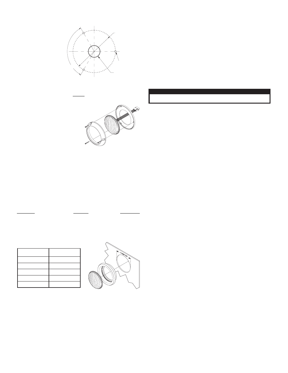
4.80” BOLT CIRCLE
MOUNTING HOLE FOR
#8 SHEET METAL SCREW
(3) PLACES TYP.
1.00” DIA
WIRE ACCESS HOLE
120°
MOUNTING CONFIGURATION
CAUTION! DO NOT LOOK DIRECTLY AT THESE LED’S WHILE THEY ARE ON.
MOMENTARY BLINDNESS AND/OR EYE DAMAGE COULD RESULT!
I M P O R TA N T W A R N I N G !
*
SYNC Patterns:
1.
SignalAlert™ 75 Phase 1
2.
SignalAlert™ 75 Phase 2
3.
CometFlash® 75 Phase 1
4.
CometFlash® 75 Phase 2
5.
DoubleFlash 75 Phase 1
6.
DoubleFlash 75 Phase 2
7.
SingleFlash 75 Phase 1
8.
SingleFlash 75 Phase 2*
9.
ComAlert™ 75 Phase 1
10. ComAlert™ 75 Phase 2
11. LongBurst™ 75 Phase 1
12. LongBurst™ 75 Phase 2
13. PingPong™ 75 Phase 1
14. PingPong 75 Phase 2
Standard Patterns:
1.
SingleFlash 60*
2.
SingleFlash 90*
3.
SingleFlash 120*
4.
SingleFlash 300
5.
DoubleFlash 150
6.
ComAlert™150
7.
ActionFlash™1
8.
ActionFlash 2
9.
ModuFlash™
10. ActionScan™
11. Steady
IMPORTANT! Before returning the vehicle to active service, visually confirm the proper operation of this product, as well as all vehicle components/equipment.