Light head wiring diagrams b/t/t light head, Grommet mounting / hole chart – Whelen 20R00XRR User Manual
Page 2
Page 2
Light
Head
Wiring Diagrams
B/T/T
Light
Head
LED Color (12V)*
LED Color (24V)**
*fuse @ 3 Amp (see note at right)
**fuse @ 1 Amp (see note at right)
YEL (12V)
YEL (24V)
BLK (12V)
BLK/WHT (24V)
BRN (12V)
BRN (24V)
WHT/VIO (12V)
WHT/VIO (24V)
WHT/VIO (12V)
WHT/VIO (24V)
WHT (12V)
WHT/BLK (24V)
+BAT
Brake/Turn
GROUND
Tail
Scan-Lock™
Scan-Lock™
GROUND
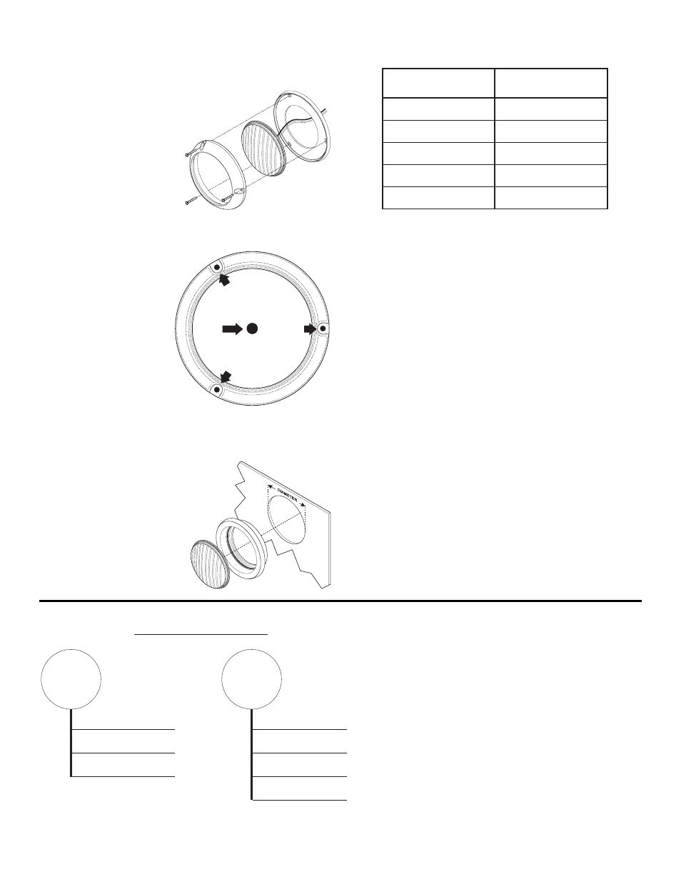
Flange Mount:
Make sure the lighthead will not interfere with existing equipment and be
aware of any items on the opposite side of the mounting surface.
1.
Position the flange against
the proposed mounting
location and then, (using a
scribe or similar tool), mark off
the 3 mounting holes. Also
mark off an area in the center
where the 1” wire passage
hole will be drilled.
IMPORTANT: Always check all
measurements before drilling.
2.
Using a drill bit sized for a #8
sheet metal screw (and the thickness of the mounting surface) drill
the 3 mounting holes.
3.
Drill a 1” dia. wire passage
hole in the area marked.
Be sure to install a
grommet (customer
supplied) into this hole.
Using appropriately sized
wires (minimum 18 AWG),
extend the lighthead wires
to their designations. Fuse
the +12VDC connections at
3 Amps and test the
lighthead, then secure it to
the vehicle with the
supplied mounting
hardware.
Grommet Mount:
Make sure the lighthead will not interfere with existing equipment and be
aware of any items on the opposite side of the mounting surface.
1.
Mark the center of the
mounting location onto the
mounting surface. Scribe a
circle onto the mounting
surface using this point as the
center. Refer to the grommet
mounting hole chart for the
proper diameter.
MOUNTING
HOLE
MOUNTING
HOLE
MOUNTING
HOLE
WIRE
HOLE
This product draws significantly less current than a
standard incandescent automotive bulb. If your flasher
does not operate properly, it may be necessary to replace
your existing flasher module with a Whelen 3TERM
flasher.
NOTE: All customer supplied wires must be sized to
supply at least 125% of the maximum operating
current and be sized at the battery to carry the load.
2.
Cut the grommet hole out and deburr it.
3.
Using appropriately sized wires (Minimum 18 AWG), extend the
lighthead wires to their designations. Fuse the +12VDC connections
at 3 Amps and test the lighthead before securing it to the vehicle.
4.
Insert the lighthead into the grommet then secure it to the vehicle by
snapping the grommet into the mounting hole as shown above.
Scan-Lock™ Operation (Brake/Tail/Turn Only):
To cycle through all patterns: Apply Positive (+) voltage to the WHITE-
VIOLET wire for less than 1 second and release to cycle forward. Apply
Positive (+) voltage for more than 1 second and release to cycle
backward.
To set a pattern as default: When the desired pattern is displayed, allow
it to run for more than 5 seconds. The beacon will now display this pattern
when activated.
To reset to the factory default pattern: Turn off power. Now, while
applying Positive (+) voltage to the WHITE-VIOLET wire, turn power back
on.
Available Patterns:
Steady
SignalAlert™ Steady
Mounting Surface
Thickness
.0625” (1/16”)
.125” (1/8”)
.1875” (3/16”)
.25” (1/4”)
.375” (3/8”)
Mounting Hole
Diameter
4.47”
4.50”
4.50”
4.53”
4.56”
GROMMET MOUNTING / HOLE CHART