Whelen 4V3A User Manual
Whelen For the car
For warranty information regarding this product, visit
www.whelen.com/warranty
©2013 Whelen Engineering Company Inc.
Form No. 14752 (121813)
NOTICE! Prior to installing on any vehicle, check your state motor vehicle codes to
confirm that this product complies with any and all state statutes.
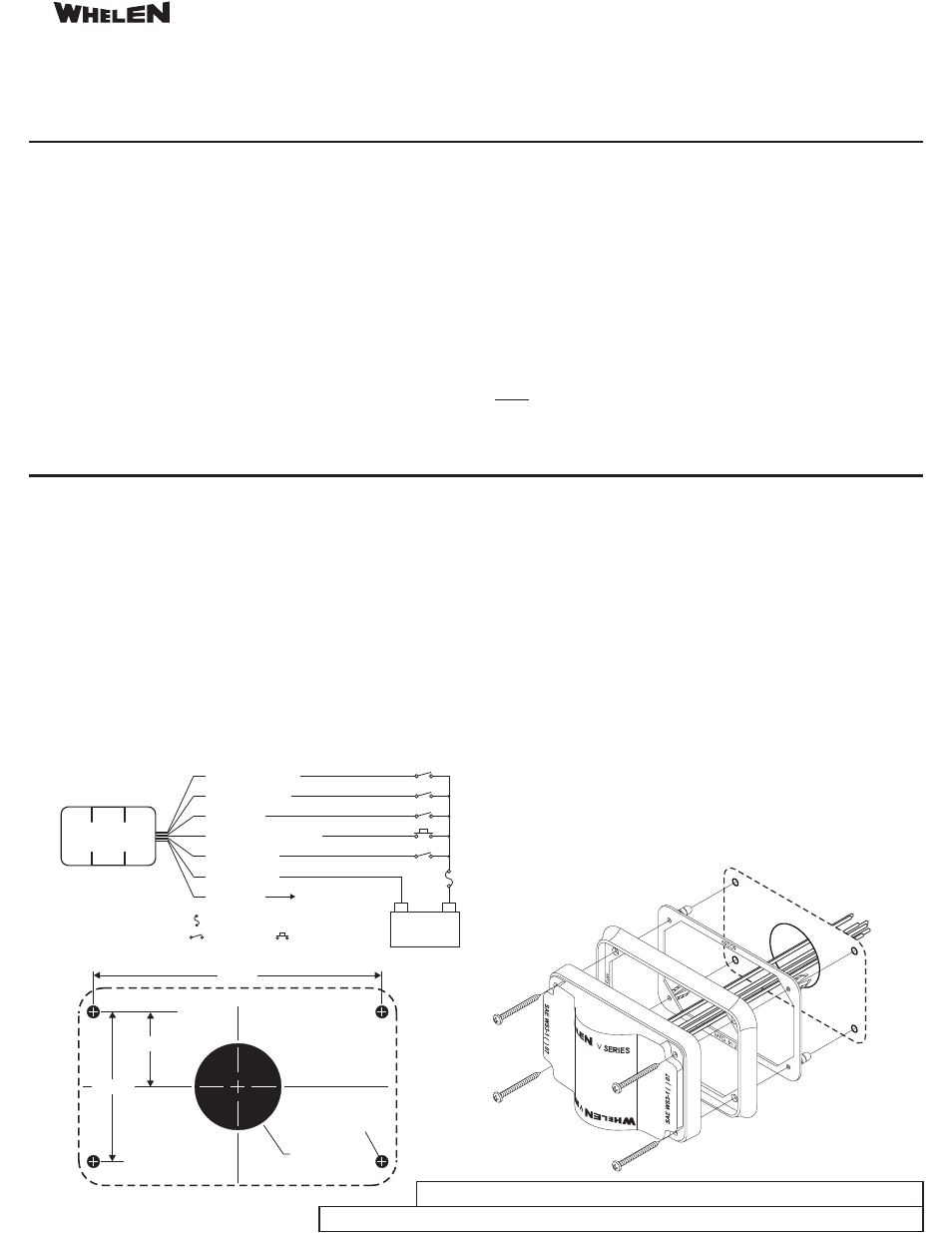
Installation: Refer to the diagrams shown for mounting measurements specific to your
model.
1. Using the mounting diagram shown, mark the locations for the mounting holes and the
wire passage hole. Using a .250" drill bit, drill 4 mounting holes. Drill and de-burr a 1.75”
dia. wire passage hole in the location shown.
2. Insert the screw grommet flange into the mounting holes as shown.
3. Using appropriately sized wire, extend the wires through the gasket and through the wire
passage hole. Make the appropriate connections (see wiring diagram for fusing
information) and confirm proper operation of the light.
4. Combine the lighthead and trim flange in the order shown. While holding these
components together, place this assembly onto the screw grommet flange.
5. Hold the components firmly against the mounting surface and secure to the mounting
surface using the hardware provided.
.
Wiring:
For replacement part numbers and other helpful information, visit www.whelen.com/install
Operation:
Scan-Lock™:
SYNC Operation:
NOTE:
Some of the patterns available for the standard SYNC lighthead are
described as being either Phase 1 (PH.1) or Phase 2 (PH.2). These terms define how
patterns on lightheads with their SYNC wires connected relate to each other. Lightheads
configured to display the same Phase of a given pattern (Phase 1 or Phase 2) will flash
simultaneously. Lightheads configured to Phase 2 of a given pattern will alternate with Phase
1 lightheads. A normally open momentary switch is best suited for this use.
The SYNC wire can be connected to other SYNC-capable power supplies to
synchronize their output. Be sure to cap the SYNC wire if it is not used.
To advance pattern: With the lighthead active, apply +VBAT to the WHT/VIO
wire for less than 1 second. To cycle to previous patterns: Apply +VBAT for more than 1
second. To restore factory default pattern: Turn off power to the lighthead. Apply +VBAT to the
WHT/VIO wire while turning the lighthead on. Continue to apply voltage to the WHT/VIO wire
for 5 seconds.
To reduce the light output for nighttime operation, apply +12VDC to the
VIO wire. Remove voltage to restore full light output. A Single Pole/Single Throw switch is
best suited for this use.
Hi-Lo Operation:
1. SignalAlert™75. . . PH.1
2. SignalAlert™
PH.2
. CometFlash®
PH.2
. DoubleFlash
PH.2
. SingleFlash
PH.1
. SingleFlash
PH.2
9. ComAlert™75 . . . . PH.1
1 . ComAlert™
PH.2
. LongBurst™
. . . PH.1
2. LongBurst™
PH.2
. PingPong™
PH.1
. PingPong™
PH.2
75. . .
3. CometFlash®75 . . PH.1
4
75 . .
5. DoubleFlash 75. . . PH.1
6
75. . .
7
75 . . .
8
75 . . .
0
75 . . . .
11
75
1
75 . . .
13
75. . . .
14
75. . . .
18. SingleFlash 300
19
21. ActionFlash™ 1
22. ActionFlash™ 2
23. ModuFlash™
24. ActionScan™
15. SingleFlash 60
16. SingleFlash 90
17. SingleFlash 120
25. Steady
. DoubleFlash 150
20. ComAlert™150
Patterns:
®
ENGINEERING COMPANY INC.
51 Winthrop Road
Chester, Connecticut 06412-0684
Phone: (860) 526-9504
Fax: (860) 526-4078
Sales Email:[email protected]
Canadian Sales:[email protected]
Customer Service:[email protected]
www.
.com
400 V-Series™ Lighthead
Safety First: This document provides all the necessary information to allow your Whelen product to be properly and safely installed. Before beginning the installation
and/or operation of your new product, the installation technician and operator must read this manual completely. Important information is contained herein that could
prevent serious injury or damage.
·
·
·
·
·
·
Proper installation of this product requires the installer to have a good understanding of
automotive electronics, systems and procedures.
Failure to use specified installation parts and/or hardware will void the product warranty!
If mounting this product requires drilling holes, the installer MUST be sure that no vehicle
components or other vital parts could be damaged by the drilling process. Check both
sides of the mounting surface before drilling begins. Also de-burr any holes and remove
any metal shards or remnants. Install grommets into all wire passage holes.
Do not install this product or route any wires in the deployment area of your air bag.
Equipment mounted or located in the air bag deployment area will damage or reduce the
effectiveness of the air bag, or become a projectile that could cause serious personal
injury or death. Refer to your vehicle owner's manual for the air bag deployment area. The
User/Installer assumes full responsibility to determine proper mounting location, based
on providing ultimate safety to all passengers inside the vehicle.
For this product to operate at optimum efficiency, a good electrical connection to chassis
ground must be made. The recommended procedure requires the product ground wire to
be connected directly to the NEGATIVE (-) battery post.
Whelen Engineering recommends the use of waterproof butt splices and/or connectors if
that connector could be exposed to moisture.
·
·
·
·
·
·
WARNING! All customer supplied wires that connect to the positive (+) terminal of the
battery must be sized to supply at least 125% of the maximum operating current and
“at the battery” to carry that load. DO NOT USE CIRCUIT BREAKERS WITH THIS
PRODUCT!
FUSED
Do not attempt to activate or control this device in a hazardous driving situation.
If this product uses a remote device to activate or control this product, make sure that this
control is located in an area that allows both the vehicle and the control to be operated
safely in any driving condition.
This product contains high-intensity LEDs. Do not stare directly into these lights.
Momentary blindness and/or eye damage could result.
Use only soap and water to clean the outer lens. Use of other chemicals could result in
premature lens cracking (crazing) and discoloration. Lenses in this condition have
significantly reduced effectiveness and should be replaced immediately. Inspect and
operate this product regularly to confirm its proper operation and mounting condition.
Do not use a pressure washer to clean this product.
FAILURE TO FOLLOW THESE PRECAUTIONS AND INSTRUCTIONS COULD RESULT IN
DAMAGE TO THE PRODUCT OR VEHICLE AND/OR SERIOUS INJURY TO YOU AND YOUR
PASSENGERS!
2.375”
1.187”
CL
4.200”
1.75" dia. hole
.250” Dia.
(4 places)
All switches and fuses
are customer supplied
To SYNC wire of other
SYNC capable lights.
GRY (Sync)
VIO (Hi-Lo)
BLK (Ground)
RED (+12VDC)
WHT/BLK (Alley)
WHT/VIO (Scan-Lock™)
WHT/RED (Puddle)
(+)
Battery
(-)
= 3A Fuse
= SP/ST Switch
= Momentary Switch
(Normally Open)
400 V-Series
Lighthead