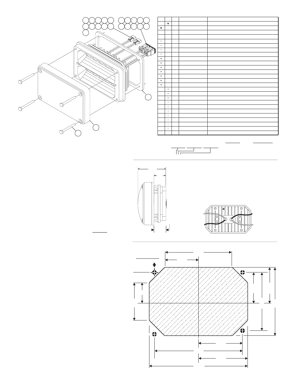
Installation, Model 400 lighthead mounting dimensions, Page 2 – Whelen 40AA5SCR User Manual
Page 2: Wiring
Page 2
1
2
24
8
3
9
4
10
5
11
6
12
13
7
19
14
20
15
21
16
22
17
23
18
2.375"
2.75"
Pilot Hole for #6
(Qty. 4)
Sheet Metal Screw
CUT-OUT
AND REMOVE
THIS AREA
CUT-OUT
AND REMOVE
THIS AREA
CUT-OUT
AND REMOVE
THIS AREA
4.60”
4.20”
.79"
1.58"
1.685"
3.37"
2.30”
1.375"
2.10”
1.187"
Model 400 Lighthead
Mounting Dimensions
BLACK
(Lower LED)
(-) Ground
LED COLOR
(Upper LED)
+12 Volts
Lighthead / Rear View
LED COLOR
(Lower LED)
+12 Volts
BLACK
(
LED)
Upper
(-) Ground
BLACK
NEGATIVE / Ground:
POSITIVE / +12 VDC: Wire color is whatever the color
of the LED is when the lighthead is switched on.
(AMBER, BLUE, WHITE, GREEN or RED)
WIRING:
CONNECTOR
BASIC P/N
LED COLOR 1 LED COLOR 2
0 1 - 0 6 6 3 7 8 3 _ _ _
CONNECTOR:
2 =
=
2 POS AMP
4 2 POS DEUTSCH
LED COLOR 1 or 2:
1 = AMBER
2 = BLUE
3 = WHITE
4 = GREEN
5 = RED
PART NUMBER KEY:
IMPORT
ANT
:
1¼
”Minimum
Required
M
ounting
Depth
ITEM
PART NUMBER
DESCRIPTION
QTY QTY
2
3
11
12
13
14
15
16
17
18
19
20
21
22
23
4
5
6
7
8
9
10
1
SUB ASSY 400 LED SPLIT GRN/GRN/AMP
/
SUB ASSY 400 LED SPLIT WHT/RED/AMP
/
SUB ASSY 400 LED SPLIT BLU/RED/AMP
/
SUB ASSY 400 LED SPLIT BLU/WHT/AMP
/
SUB ASSY 400 LED SPLIT AMB/RED/AMP
/
SUB ASSY 400 LED SPLIT AMB/WHT/AMP
/
SUB ASSY 400 LED SPLIT AMB/BLU/AMP
/
SUB ASSY 400 LED SPLIT WHT/WHT/AMP
/
SUB ASSY 400 LED SPLIT RED/RED/AMP
/
SUB ASSY 400 LED SPLIT BLU/BLU/AMP
/
SUB ASSY 400 LED SPLIT AMB/AMB/AMP
/
LENS CLEAR NON OPTIC W/ SEAL
/
SCREW #6 X 1-1/2" PPHSMS
/
SUB ASSY 400 LED SPLIT AMB-AMB DEUTSCH
/
/
SUB ASSY 400 LED SPLIT BLU-BLU DEUTSCH
/
/
LIGHTHEAD 400 Linear-LED® / AMP
LIGHTHEAD 400
DEUTSCH
Linear-LED®
4
1
4
1
A/R
A/R
A/R
A/R
A/R
A/R
A/R
A/R
A/R
A/R
A/R
A/R
A/R
0 1 - 0 2 8 6 3 6 1 2 5 5
0 1 - 0 2 8 6 3 6 1 2 3 3
0 1 - 0 2 8 6 3 6 1 2 2 2
0 1 - 0 2 8 6 3 6 1 2 11
6 8 - 3 1 8 3 7 2 5 - 3 S
1 5 - 0 6 1 4 1 6 - 2 4 0
0 1 - 0 2 8 6 3 6 1 2 4 4
0 1 - 0 2 8 6 3 6 1 4 2 2
0 1 - 0 2 8 6 3 6 1 2 3 5
0 1 - 0 2 8 6 3 6 1 2 2 5
0 1 - 0 2 8 6 3 6 1 2 2 3
0 1 - 0 2 8 6 3 6 1 2 1 5
0 1 - 0 2 8 6 3 6 1 2 1 3
0 1 - 0 2 8 6 3 6 1 2 1 2
0 1 - 0 2 8 6 3 6 1 4 11
GASKET SURFACE MOUNTING
/
SUB ASSY / 400 LED SPLIT WHT-RED / DEUTSH
SUB ASSY 400 LED SPLIT BLU-RED DEUTSCH
/
/
SUB ASSY 400 LED SPLIT BLU-WHT DEUTSCH
/
/
SUB ASSY 400 LED SPLIT AMB-WHT DEUTSCH
/
/
SUB ASSY 400 LED SPLIT AMB-BLU DEUTSCH
/
/
SUB ASSY 400 LED SPLIT RED-RED DEUTSCH
/
/
SUB ASSY 400 LED SPLIT WHT-WHT DEUTSCH
/
/
SUB ASSY 400 LED SPLIT AMB-RED DEUTSCH
/
/
A/R
A/R
A/R
A/R
A/R
A/R
A/R
A/R
1
1
0 1 - 0 2 8 6 3 6 1 4 2 5
0 1 - 0 2 8 6 3 6 1 4 3 5
0 1 - 0 2 8 6 3 6 1 4 2 3
0 1 - 0 2 8 6 3 6 1 4 1 5
0 1 - 0 2 8 6 3 6 1 4 1 3
0 1 - 0 2 8 6 3 6 1 4 1 2
0 1 - 0 2 8 6 3 6 1 4 3 3
0 1 - 0 2 8 6 3 6 1 4 5 5
3 8 - 0 4 6 3 9 2 4 - 0 0
0 1 - 0 6 6 3 7 8 3 2 _ _
0 1 - 0 6 6 3 7 8 3 4 _ _
24
1.98"
.83"
IMPORTANT
NOTICE! This product has been
designed for improved visibility. Prior to installing
this product on any vehicle, check your state
motor vehicle codes to confirm that this product
complies with all state statutes.
WARNING! The LED must be connected to an
electronic flasher. Allowing the LED to steady
burn will damage the lighthead and void the
warranty.
WARNING! All customer supplied wires that
connect to the positive terminal of the battery
must be sized to supply at least 125% of the
maximum operating current and FUSED at the
battery to carry that load. DO NOT USE CIRCUIT
BREAKERS WITH THIS PRODUCT!
Installation:
1.
Position the lighthead in its approximate mounting
location to make sure that the lighthead will not interfere
with any existing equipment. Also be aware of any and
all items on the opposite side of the mounting surface to
prevent any possible damage to existing components. A
1¼” minimum mounting depth is required.
2.
Remove the lighthead. Measure and mark the mounting
holes off onto the mounting surface and cut-out as
shown.
3.
Using an appropriately sized drill bit for a #6 sheet metal
screw, drill the 4 pilot holes.
4.
Cut out and remove the area indicated in the mounting
dimensions.
5.
Route the wires to power (cables are customer
supplied).
6.
Plug the lighthead in and test the operation before
securing it to the vehicle.
7.
Secure the assembly onto the mounting surface with
the supplied sheet metal screws.