Mounting, Scan-lock™ (white/violet) – Whelen 400 Series LED Lighthead User Manual
Page 2
Page 2
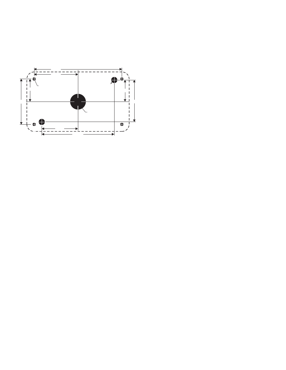
1" Dia. Hole
Mounting hole
for #6 sheet metal
screws (4 places)
2.100"
4.200"
1.187"
2.375"
1.070"
2.140"
1.735"
3.470"
.312"
DIA HOLE
.
(2) PLACES
1" DIA.
WIRE
HOLE
Caution: This product is designed for improved visibility. Prior to
installing this product on any vehicle, check your state
motor vehicle codes to confirm that this product
complies with any and all state statutes.
Mounting:
1.
Using the dimensions below, mark off and drill the two 5/16”
diameter vent tube holes and the 1” center wire hole into the
mounting surface. Check measurements before drilling.
Note: Make sure lighthead will not interfere with existing
equipment and be aware of any items on the opposite side
of the mounting surface.
2.
Insert the 2 vent tubes extending from the rear of the lighthead
into their holes. With a scribe or similar tool, mark off the 4
mounting holes.
3.
Using a drill bit sized for a #6 sheet metal screw (and the
thickness of the mounting surface), drill the four mounting holes.
Install a grommet (customer supplied) into the 1” wire hole.
4.
Using appropriately sized wires (minimum 18 AWG wire size),
run the lighthead wires to their connections (see wire
designations on pg. 3). Fuse the +VBAT connections at 3 Amps
and test operation of lighthead before securing it to vehicle.
5.
Position the lighthead onto the mounting surface and secure to
the vehicle using four #6 x 1-1/4” sheet metal screws.
Caution: WARNING! All customer supplied wires that connect to
the positive terminal of the battery must be sized to
supply at least 125% of the maximum operating current
and FUSED at the battery to carry the load. DO NOT
USE CIRCUIT BREAKERS WITH THIS PRODUCT!
Caution: This product draws significantly less current than a
standard incandescent automotive bulb. If your flasher
does not operate properly, it may be necessary to
replace your existing flasher module with a Whelen
3TERM flasher module. Contact your sales
representative for specific vehicle application.
Scan-Lock™ (White/Violet)
WARNING: Pattern selection requires the LED to be turned on.
Do not look directly at LEDs while the unit is in operation.
IMPORTANT: If you have a 24 volt lighthead, you will apply 24
volts to the Scan-Lock wire for flash pattern selection.
TO CHANGE PATTERNS: Apply +12 volts to the WHITE/VIOLET
wire for less than 1 second and release to cycle forward to the next
available pattern. Apply +12 volts to the WHITE/VIOLET wire for more
than 1 second and release to cycle back to the previous pattern.
TO CHANGE THE DEFAULT PATTERN: When the desired pattern is
displayed, allow it to run for more than 5 seconds. The lighthead will
now display this pattern when initially activated.
TO RESTORE THE FACTORY DEFAULT PATTERN: With the power
to the lighthead off, apply +12 volts to the WHITE/VIOLET wire. Now
turn power to the lighthead on. The factory default pattern should now
be displayed.
NOTE: A Normally Open momentary switch can be used to
control Scan-Lock™ operation.
Flash Patterns: SignalAlert™ 75 > SignalAlert™ 150 > SingleFlash
375 > SingleFlash 150 > SingleFlash 75 > SingleFlash 150 >
DoubleFlash 150 > DoubleFlash 75 > CometFlash® 75 >
ActionFlash™ > ModuFlash™ > ComAlert™ > ActionScan™ >
SignalAlert™ Steady > Steady (Brake) Available Brake Patterns:
SignalAlert™ Steady > Steady Brake
IMPORTANT! Before returning this vehicle to active service,
visually confirm the proper operation of this product, as well as
all vehicle components/equipment.