Wiring, Installation, Page 2 – Whelen 40A02ZAR User Manual
Page 2
Page 2
1
FLASHER REQUIREMENT
2 =
4 =
EXTERNAL
ON-BOARD
LED/LENS COLOR
1 =
2 =
3 =
AMBER/CLEAR
BLUE/CLEAR
WHITE/CLEAR
GREEN/CLEAR
RED/CLEAR
AMBER/AMBER
4 =
5 =
A =
CONNECTOR
0 =
1 =
NONE
3 POS DEUTSCH
WIRING DIAGRAM
POS A -
POS B -
POS C -
LOOSE -
3 POS Deutsch Socket Housing
LED Color Wire
GREY
BLACK
WHITE/VIOLET
B
C
A
8-17
21
18
A/R A/R
400 LINEAR TIR LED - GREEN/4-WIRE
SCREW, #6 X 1 1/2 PPHSMS
OPTIC LENS - LENS RED
OPTIC LENS - LENS GREEN
OPTIC LENS - LENS CLEAR
OPTIC LENS - LENS BLUE
LIGHTHEAD, 400 LINEAR TIR LED 4-WIRE/DEUTSCH
400 LINEAR TIR LED - GREEN/2-WIRE
400 LINEAR TIR LED - AMBER/2-WIRE
400 LINEAR TIR LED - BLUE/2-WIRE
400 LINEAR TIR LED - WHITE/2-WIRE
400 LINEAR TIR LED - RED/2-WIRE
LIGHTHEAD, 400 LINEAR TIR LED 4-WIRE
400 LINEAR TIR LED - WHITE/4-WIRE
400 LINEAR TIR LED - BLUE/4-WIRE
400 LINEAR TIR LED - AMBER/4-WIRE
OPTIC LENS - LENS AMBER
LIGHTHEAD, 400 LINEAR TIR LED 2-WIRE
0 1 - 0 6 6 B 5 6 9 2 _ 0
A/R
A/R
A/R
A/R
A/R
A/R
A/R
A/R
A/R
A/R
A/R A/R
4
4
A/R
A/R
A/R
A/R
A/R
A/R
A/R
A/R
A/R
A/R
A/R A/R
A/R
A/R
1 5 - 0 6 1 4 1 6 - 2 4 0
0 1 - 0 6 6 B 5 6 9 4 _ 1
0 1 - 0 6 6 B 5 6 9 4 _ 0
6 8 - 11 8 3 7 2 6 A 1 S
4
not sold seperatly
WEDGE, 3 POS DEUTSCH
HOUSING, 3 POS SOCKET DEUTSCH
SOCKET, DEUTSCH
400 LINEAR TIR LED - RED/4-WIRE
A/R A/R
3
1
1
1
1
3 8 - 0 4 6 3 9 2 4 - 0 0
3 9 - 1 H 1 6 4 2 4 - 3 S
3 9 - 1 H 0 3 0 2 4 - 3 5
3 9 - 1 H 0 0 3 2 6 - 3 5
1
GASKET
not sold seperatly
not sold seperatly
not sold seperatly
not sold seperatly
not sold seperatly
not sold seperatly
not sold seperatly
not sold seperatly
not sold seperatly
6 8 - 11 8 3 7 2 6 A 2 S
6 8 - 11 8 3 7 2 6 A 3 S
6 8 - 11 8 3 7 2 6 A 4 S
6 8 - 11 8 3 7 2 6 A 5 S
OPTIC LENS - ECE BLUE
A/R
6 8 - 11 8 3 7 2 6 A 5 S
2
3
ITEM
PART NUMBER
DESCRIPTION
QTY QTY QTY
11
12
13
14
15
16
17
18
19
20
4
5
6
7
8
9
10
1
21
2
4
3
5 6 7
BLUE/BLUE
GREEN/GREEN
RED/RED
B =
G =
R =
19
20
FLASHER REQ.
LED/LENS COLOR
PART NUMBER KEY:
0 1 - 0 6 6 B 5 6 9 _ _ _
CONNECTOR
Positive / +12V
Ground
SYNC
Scan-Lock™
WIRE FUNCTIONS
olor
/ On-Board Flasher
LED C
-
BLACK -
GREY -
WHITE-VIOLET -
WIRE FUNCTIONS
olor
:
LED C
-
BLACK -
External Flasher
Positive / +12V
Ground
To +VBAT
SYNC
GROUND
Scan-Lock™
RED
GREY
WHITE-VIOLET
3 Amp Fuse (Customer Supplied)
BLACK
Wiring:
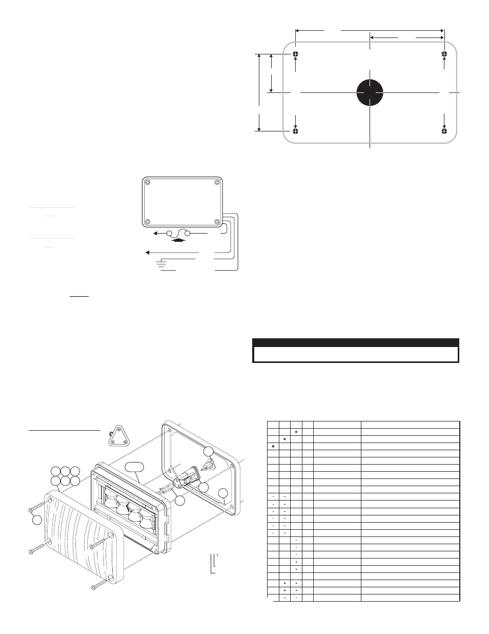
2.100"
4.200"
1.187"
2.375"
Model 400 LED Series Mounting Dimensions
NOTE: THIS IS NOT A TEMPLATE
AND IS NOT DRAWN TO SCALE.
Mounting
hole
for
#6
Sheet
Metal
Screws.
(4
Places)
Mounting
hole
for
#6
Sheet
Metal
Screws
(4
Places)
1" DIA.
WIRE
HOLE
Installation:
WARNING! The LED models designated external flasher must be connected to
an electronic flasher. Allowing the LED to steady burn will damage the
lighthead and void the warranty.
External Flasher Models: This product draws significantly less current than a
standard incandescent automotive bulb. If your flasher does not operate properly, it
may be necessary to replace your existing flasher module with a Whelen 3TERM
flasher module. Contact your sales representative for specific vehicle application.
Caution: Permanent mounting of this product will require drilling. It is
absolutely necessary to make sure that no other vehicle components could be
damaged by this process. Check both sides of the mounting surface before
starting. If damage is likely, select a different mounting location.
1.
Follow the dimensions shown. On the mounting surface, mark off and drill four
mounting holes for a #6 sheet metal screw and a 1” wire passage hole in the
center. Always check all measurements before drilling.
2.
Using appropriately sized wires (minimum wire size / 18 AWG), extend the
lighthead wires to their connections. Fuse the +12VDC connections at 3 Amps
and test operation of lighthead before securing it to vehicle.
3.
Position the lighthead onto the mounting surface and secure to the vehicle
using four #6 x 1-1/2” sheet metal screws.
WARNING! All customer supplied wires that connect to the positive terminal of
the battery must be sized to supply at least 125% of the maximum operating
current and be FUSED at the battery to carry that load. DO NOT USE CIRCUIT
BREAKERS WITH THIS PRODUCT!
Scan-Lock™: 400 Series lightheads (with 4 wires) have a special set of flash
patterns, with each pattern available in two modes; Phase 1 and Phase 2. The
patterns are changed with the WHITE-VIOLET wire.
When the lighthead is turned on, the default pattern is displayed.
To advance to the next pattern: With the lighthead on, apply positive voltage to the
WHITE-VIOLET wire for less than 1 second and release. Repeat the procedure to
advance the lighthead to the next pattern.
To lock in a pattern. While cycling through the patterns, let a pattern run for more
than 5 seconds and it will become the default pattern.
To cycle backwards to previous patterns: With the lighthead on, apply positive
voltage to the WHITE-VIOLET wire for more than 1 second and release.
To reset to the factory default pattern: Turn off power to the lighthead. While
applying positive voltage to the WHITE-VIOLET wire, turn the lighthead back on.
Continue to apply voltage to the WHITE-VIOLET wire for 5 seconds.
Using the SYNC feature with more than 2 lightheads: To understand how to use
the SYNC feature with more than 2 lightheads, the principles will be applied to a
sample system consisting of 4 lightheads. 2 are mounted on the rear, driver side of
the vehicle and 2 on the rear, passenger side of the vehicle. With all the wiring
complete, turn on the 4 lightheads. As shipped from the factory, all the lightheads will
simultaneously display the same pattern (SignalAlert™ / Phase 1).
To configure, for example, the passenger side lightheads to alternate with the driver
side lightheads, change the flash patterns for either the passenger or driver side
lightheads to Phase 2 mode of the same pattern.
IMPORTANT! SYNC-capable LED lightheads can be SYNCed to SYNC-capable
strobe power supplies (such as the CS240S) by wiring their grey wires together.
When connected as such, LED lightheads in their default pattern (simultaneous) will
flash simultaneously with strobe lightheads connected to the power supply’s GREEN
output wire. LED lightheads configured for the alternating pattern will flash
simultaneously with strobe lightheads connected to the power supply’s WHITE
output wire. GREEN output wires always alternate with WHITE output wires.
Available Flash Patterns: = California Title XIII compliant
IMPORTANT: It is the responsibility of the installation technician to make sure
that the installation and operation of this product will not interfere with or
compromise the operation or efficiency of any vehicle equipment!
IMPORTANT! Before returning the vehicle to active service, visually confirm
the proper operation of this product, as well as all vehicle components/
equipment.
SYNC Patterns:
1. SignalAlert™ 75Phase 1
2. SignalAlert 75 Phase 2
3. CometFlash®75Phase 1
4. CometFlash 75 Phase 2
5. DoubleFlash 75 Phase 1
6. DoubleFlash 75 Phase 2
7. SingleFlash 75 Phase 1
8. SingleFlash 75 Phase 2
9. ComAlert™ 75 Phase 1
10.ComAlert 75
Phase 2
11.LongBurst™75 Phase 1
12.LongBurst 75 Phase 2
13.PingPong™75 Phase 1
14.PingPong 75
Phase 2
Regular Patterns:
15. SingleFlash 60
16. SingleFlash 90
17. SingleFlash 120
18. SingleFlash 300
19. DoubleFlash 150
20. ComAlert™150
21. ActionFlash™1
22. ActionFlash 2
23. ModuFlash™
24. ActionScan™
25. Steady
*
*
*
*
*
CAUTION! DO NOT LOOK DIRECTLY AT THESE LED’S WHILE THEY ARE ON.
MOMENTARY BLINDNESS AND/OR EYE DAMAGE COULD RESULT!
I M P O R TA N T W A R N I N G !