Fig. 1, Fig. 3, Fig. 2 – Whelen 4ILKT1 User Manual
Page 2: Fig. 4
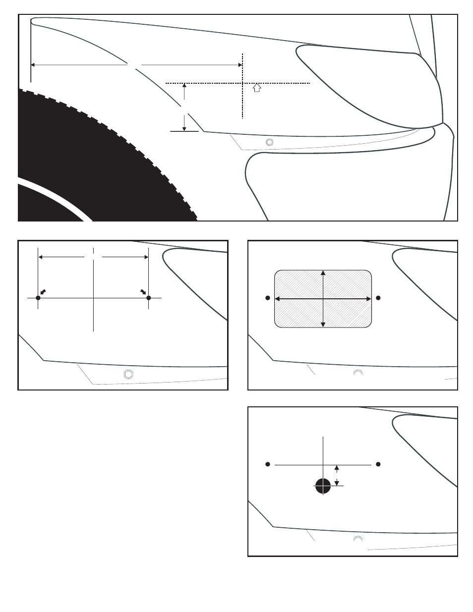
Page 2
FRONT
WHEEL
WELL
FRONT FENDER
FRONT TIRE
HEADLIGHT
G
R
I
L
L
Outside view of right (passengers)
side of vehicle shown.
First find the center point
using these dimensions.
End
of
body
panel
This line must be level with
the road.
Vehicle must
be parked on a level surface.
NOTE:
Bottom of
wheel well
4.5"
14"
FIG. 1
Draw these dimensions from your center line
and remove the shaded area.
FIG. 3
4.6"
4.6"
2.75"
2.75"
HEADLIGHT
Using your center line, mark off and drill two
mounting holes using a #5 or 7/32" drill.
FIG. 2
5.188"
Drill mounting
hole here.
Drill mounting
hole here.
HEADLIGHT
1" diameter
wire access hole
FIG. 4
HEADLIGHT
7/8"
STROBE OR HALOGEN LIGHTHEAD
LED LIGHTHEAD
Installation:
You will need to park the vehicle on a level surface for the
installation. As the diagram shows, the horizontal mounting hole line
must be level with the road. Draw this line using a level.
1.
Find the center line of your lighthead using the dimensions in
Figure 1. Measure from the end of the body panel and draw the
verticle line. Measure from the bottom of the wheel well and,
using a level, draw the horizontal line.
2.
Measure and drill the 2 mounting holes (Fig. 2).
3.
If you are installing a strobe or halogen lighthead measure out
from the center line and cut-out and remove the area shown in
Figure 3 . If you have an LED lighthead you will just need to drill
a 1” wire hole as shown in Figure 4.
4.
Attach the lighthead to the vehicle (Fig. 5). Be sure to locate the
wire exit hole (in the rear casting) on the bottom and run the
wires through before tightening the mounting bolts.
5.
Extend the lighthead wires to your power source.