Connector pinouts, Page 2 – Whelen 50A02ZAR User Manual
Page 2
Page 2
All switches and fuses
are customer supplied
All switches and fuses
are customer supplied
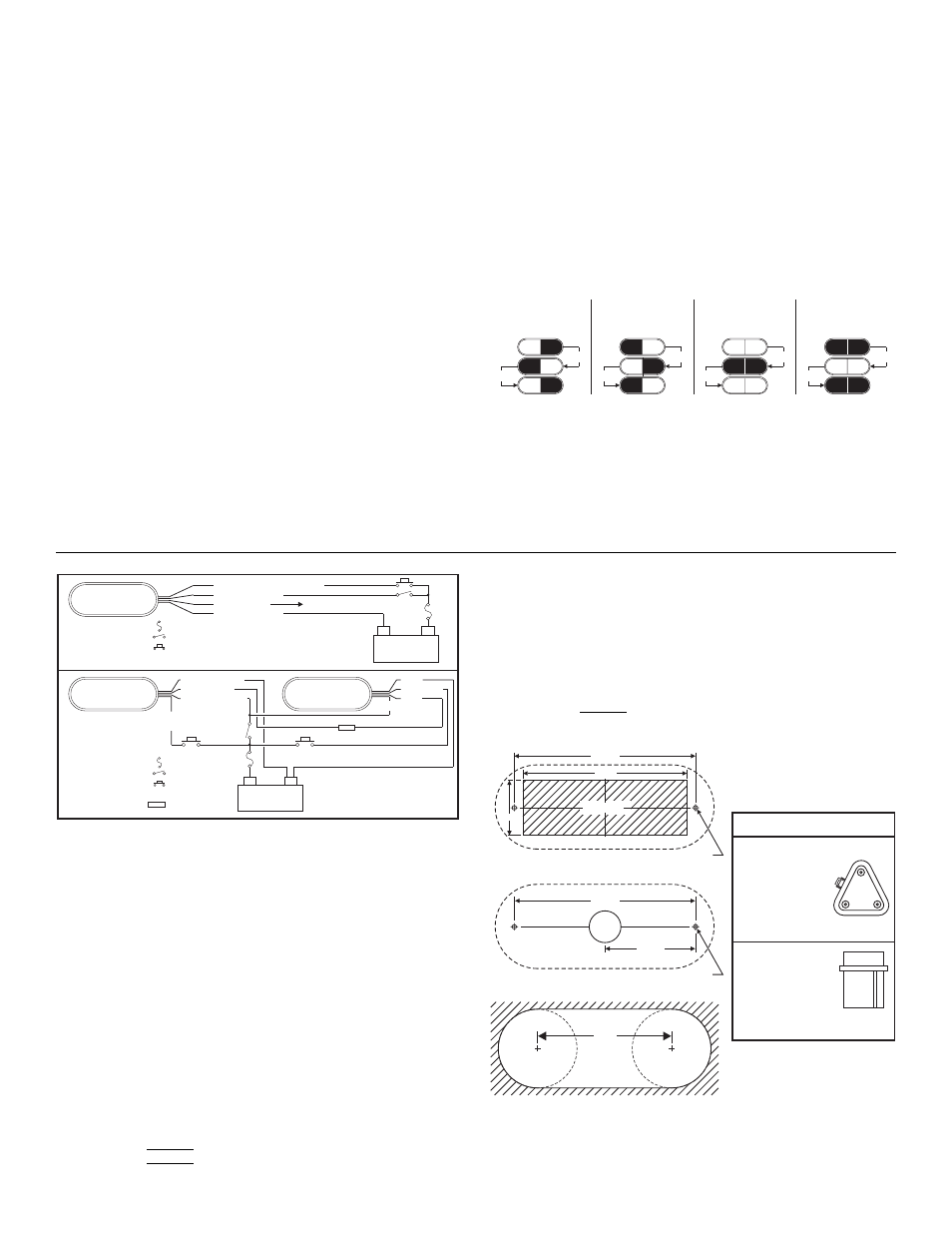
Cut & cap GRY wire
GRY (Sync)
BLK (Ground)
RED (+12VDC)
GRY (Sync)
BLK (Ground)
RED (+12VDC)
WHT/VIO (Scan-Lock™)
WHT/VIO
(Scan-Lock™)
(+)
Battery
(-)
(-)
Battery
(+)
500 Series
Lighthead
= 3A Fuse
= Momentary
Switch (N.O.)
= SP/ST Switch
= 3A Fuse
= Momentary
Switch (N.O.)
= Butt Splice
= SP/ST Switch
GRY
BLK
WHT/VIO
RED
500 Series
Lighthead
500 Series
Lighthead
Wiring
1.74
MTG. HOLE FOR #10 SCREW (2 PLCS.)
MTG. HOLE FOR #10 SCREW (2 PLCS.)
CUT-OUT
5.20
5.750
Flange Mount (5FLANGEC / 5FLANGEP / 5FLANGEB)
Flange Mount (5TSMAC / 5TSMAB / 5LSMAB / 5LSMAC)
Grommet
(5GROMMET)
Mount
5.750
2.875
1” DIA.
Wire Hole
4.25
1.25”
Radius
1.25”
Radius
A
C
B
DEUTSCH 3 POS SOCKET
POS A -
POS B -
POS C -
LOOSE -
RED (+VBAT)
GREY (SYNC)
GROUND
WHT/VIO
(SCAN-LOCK™)
AMP 3 POS PIN
POS 1 -
POS 2 -
POS 3 -
LOOSE -
RED (+VBAT)
GREY (SYNC)
GROUND
WHT/VIO
(SCAN-LOCK™)
LOOSE -
1
2
3
Connector Pinouts
PHASE 1
LEFT
RIGHT
side lights up and
with
side.
alternates
PHASE 2
RIGHT
LEFT
side lights up and
with
side.
alternates
PHASE 3
BOTH sides flash together
(ON-OFF-ON).
PHASE 4
BOTH sides flash together
(OFF-ON-OFF).
Note: Phases 3 & 4 are visually indistinguishable.
then
then
ON
OFF
ON
OFF
ON
OFF
then
then
ON
OFF
ON
OFF
ON
OFF
then
then
ON ON
ON ON
OFF
OFF
then
then
ON ON
OFF
OFF
OFF
OFF
NOTICE! Prior to installing on any vehicle, check your state motor
vehicle codes to confirm that this product complies with any and all
state statutes.
Installation: Refer to the diagrams shown for mounting measurements
specific to your model.
IMPORTANT: Customer supplied wire must be a minimum of 18 gauge.
5FLANGE* Notes: Mark the mounting and cut out holes onto the
mounting surface. Drill the 2 mounting holes to the sizes noted and
remove the area that the lighthead fits into. Thread the wires through the
rubber gasket and extend to your power source. Attach the housing to
vehicle using the flange and supplied mounting hardware. Extend the
wires to your power source.
5TSMA* and 5LSMA* Notes: Mark off the measurements and drill the
wire access and mounting holes. Thread the wires through the rubber
gasket, through the wire access hole and to your power source. Attach
housing to vehicle using supplied mounting hardware and flange. Extend
the wires to your power source.
5GROMMET Notes: Mark off the measurements, drill the two 1.25” holes
and cut out the center area. Install the rubber grommet. Assemble the
flange, lighthead and adapter then snap this assembly into the grommet.
Extend the wires to your power source.
Scan-Lock™: To advance pattern: With the lighthead active, apply
+VBAT to the WHT/VIO wire for less than 1 second. To cycle to previous
patterns: Apply +VBAT for more than 1 second. To restore factory
default pattern: Turn off power to the lighthead. Apply +VBAT to the
Standard Lighthead Patterns
Split Lighthead Patterns
NOTE: BOLD = California Title XIII Compliant Pattern Italic = SYNC Patterns
NOTE: BOLD = California Title XIII Compliant Pattern Italic = SYNC Patterns
NOTE: PHASE 1 ALWAYS ALTERNATES WITH PHASE 2
NOTE: PHASE 1 ALWAYS ALTERNATES WITH PHASE 2
PHASE 3 ALWAYS ALTERNATES WITH PHASE 4
1. SignalAlert™ 75 ...... PH.1
2. SignalAlert 75 .......... PH.2
3. SignalAlert 75 .......... PH.3
4. SignalAlert 75 .......... PH.4
5. CometFlash® 75 ..... PH.1
6. CometFlash 75 ........ PH.2
7. CometFlash 75 ........ PH.3
8. CometFlash 75 ........ PH.4
9. DoubleFlash 75...... PH.1
10. DoubleFlash 75...... PH.2
11. DoubleFlash 75...... PH.3
12. DoubleFlash 75...... PH.4
13. SingleFlash 75 ....... PH.1
14. SingleFlash 75 ....... PH.2
15. SingleFlash 75 ....... PH.3
16. SingleFlash 75 ....... PH.4
17. ComAlert™ 75......... PH.1
18. ComAlert 75 ............ PH.2
19. ComAlert 75 ............ PH.3
20. ComAlert 75 ............ PH.4
21. LongBurst™ 75 ....... PH.1
22. LongBurst 75 ........... PH.2
23. LongBurst 75 ........... PH.3
24. LongBurst 75 ........... PH.4
25. PingPong™ 75 ....... PH.1
26. PingPong 75 ........... PH.2
27. PingPong 75 ........... PH.3
28. PingPong 75 ........... PH.4
29. SSNF 75 .................. PH.1
30. SSNF 75 .................. PH.2
31. SingleFlash 60......... ALT
32. SingleFlash 60..........SIM
33. SingleFlash 90......... ALT
34. SingleFlash 90..........SIM
35. SingleFlash 120....... ALT
36. SingleFlash 120........SIM
37. SingleFlash 300 .........ALT
38. SingleFlash 300 .........SIM
39. DoubleFlash 150........ALT
40. DoubleFlash 150........SIM
41. ComAlert™150 ..........ALT
42. ComAlert150..............SIM
43. ActionFlash™50 ........ALT
44. ActionFlash50 ............SIM
45. ActionFlash150 ..........ALT
46. ActionFlash150 ..........SIM
47. ModuFlash™ .............ALT
48. ModuFlash .................SIM
49. DoubleFlash 120...... ALT
50. DoubleFlash 120...... SIM
51. PingPong 120 .......... ALT
52. PingPong 120 .......... SIM
53. TripleFlash™ 75....... ALT
54. TripleFlash 75 .......... SIM
55. TripleFlash 120 ........ ALT
56. TripleFlash 120 ........ SIM
57. SigAlert Cal.............. ALT
58. SigAlert Cal.............. SIM
59. Action 1 .................... ALT
60. Action 1 .................... SIM
61. Action 2 .................... ALT
62. Action 2 .................... SIM
63. CalScan™ .........ALT/SIM
64. ActionScan™ ..... ALT/SIM
65. SteadyFlash 60
66. SteadyFlash 75
67. SteadyFlash 90
68. SteadyFlash 120
69. Steady & Steady
1. SignalAlert™ 75 .......PH.1
2. SignalAlert™ 75 .......PH.2
3. CometFlash® 75 ......PH.1
4. CometFlash® 75 ......PH.2
5. DoubleFlash 75........PH.1
6. DoubleFlash 75........PH.2
7. SingleFlash 75 .........PH.1
8. SingleFlash 75 .........PH.2
9. ComAlert™ 75 .........PH.1
10. ComAlert™ 75......... PH.2
11. LongBurst™ 75 ....... PH.1
12. LongBurst™ 75 ....... PH.2
13. PingPong™ 75 ........ PH.1
14. PingPong™ 75 ........ PH.2
15. SingleFlash 60
16. SingleFlash 90
17. SingleFlash 120
18. SingleFlash 300
19. DoubleFlash 150
20. ComAlert™150
21. ActionFlash™1
22. ActionFlash™2
23. ModuFlash™
24. ActionScan™
25. Steady
WHT/VIO wire while turning the lighthead on. Continue to apply voltage to
the WHT/VIO wire for 5 seconds.
SYNC Operation: Some of the patterns available for the standard SYNC
lighthead are described as being either Phase 1 (PH.1) or Phase 2 (PH.2).
These terms define how patterns on lightheads with their SYNC wires
connected relate to each other. Lightheads configured to display the same
Phase of a given pattern (Phase 1 or Phase 2) will flash simultaneously.
Lightheads configured to Phase 2 of a given pattern will alternate with
Phase 1 lightheads.
Split lightheads have 2 additional phases. Their operation is more easily
understood using the following illustration:
Split Lighthead Operation
NOTE: The SYNC wire can be connected to other SYNC-capable power
supplies to synchronize their output.
Be sure to cap the SYNC wire if it is not used.
IMPORTANT! Before returning the vehicle to active service, visually
confirm the proper operation of this product, as well as all vehicle
components/equipment.