Installation – Whelen 500 Series Halogen Lighthead User Manual
Page 2
Page 2
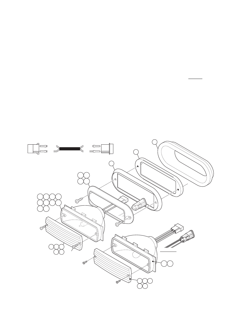
#6 X 1/2 PPH THREAD
FORMING SCREW
#10 X 3/4
PPHSMS
14 15 16
17 18
2 3 4 5
10 11
6 7 8 9
12 13
25
21
22
19 20
23 24
16
15
14
18
17
3-wire Note:
RED.......
BLACK..
WHITE...
Tail
Brake
Ground
Installation:
1.
Position the lighthead in its approximate mounting location and make sure that the lighthead will not interfere with any
existing equipment. Also be aware of any items on the opposite side of the mounting surface to prevent any possible
damage to existing components.
2.
Using the measurements supplied, mark off the mounting holes and lighthead cut-out hole onto the mounting surface.
3.
Drill the 2 screw holes and cut the mounting hole out as indicated.
4.
Wire the lighthead as shown below and secure it to the mounting location using the supplied sheet metal screws.
Note:
All customer supplied wires that connect to the positive terminal of the battery must be
sized to supply at least 125% of the maximum operating current and FUSED at the battery
to carry that load. DO NOT USE CIRCUIT BREAKERS WITH THIS PRODUCT!
Caution:
The replacement of any halogen bulb requires the use of safety glasses to prevent injury.
Do not handle the bulb with bare hands. Use gloves to prevent possible injuries.
IMPORTANT!
Before returning this vehicle to active service, visually confirm the proper operation of this product,
as well as all vehicle components/equipment.
RED
WHITE
WHITE
RED
NOTE: This cable is shown for reference only and is not included.
RED WIRE- POSITION #1 / WHITE WIRE- POSITION #3
POWER SUPPL
Y
LIGHT
HEAD