Installation, Pattern selection – Whelen 5SA00FAR User Manual
Page 2
Page 2
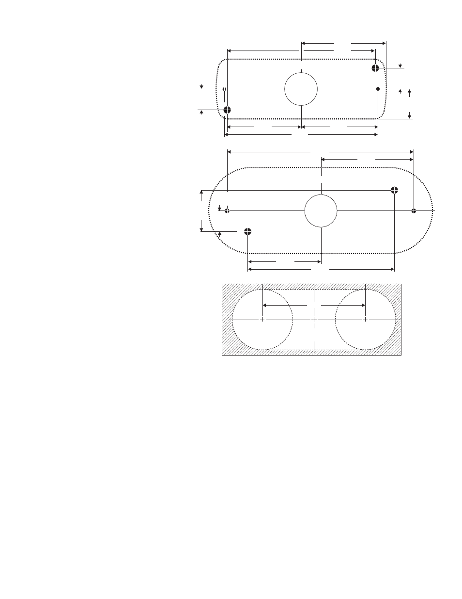
500 Series
D.O.T. Grommet
1.25" RADIUS
4.25"
1.25" RADIUS
5.750"
1/4" DIA.
VENT HOLE
1/4" DIA.
VENT HOLE
1" DIAMETER
WIRE. HOLE
MTG. HOLE
FOR #10
SCREW
MTG. HOLE
FOR #10
SCREW
4.527"
2.875"
1.274"
.637"
2.264"
500 Series / Flanged
MTG. HOLE
FOR #6 SMS
MTG. HOLE
FOR #6 SMS
1/4" DIA.
VENT HOLE
500 Series / Non-Flanged
1/4" DIA.
VENT HOLE
.637"
.637"
.912"
2.264"
4.690"
2.345"
2.597"
4.527"
MOUNTING
S
URF
ACE
MOUNTING
S
URF
ACE
1" DIAMETER
WIRE. HOLE
IMPORTANT NOTICE! Prior to installing this
product on any vehicle, check your state
motor vehicle codes to confirm that this
product complies with all state statutes.
Installation:
1. First, mark the mounting, wire access and vent
holes using the measurements shown. Drill the
holes to the sizes noted.
IMPORTANT: Templates are not to scale. Check all
measurements before drilling.
2. Thread the wires through the rubber gasket, through
the wire access hole and to your power source. Use
a rubber grommet (customer supplied) to protect the
wires from the edge of the wire access hole.
Wire designations are listed on the next page.
3. Attach light to vehicle using the supplied hardware.
4. Connect the lighthead wires to your power source.
IMPORTANT: Any customer supplied wire must be
a minimum of 22 gauge.
NOTE: This product draws significantly less
current than a standard automotive bulb. If your
flasher does not operate properly, it may be
necessary to replace your existing flasher module
with a Whelen 3TERM flasher module. Contact
your sales representative for specific vehicle
information.
Pattern Selection:
WARNING: PATTERN SELECTION REQUIRES THE
LED TO BE TURNED ON. DO NOT LOOK
DIRECTLY AT LEDs WHILE UNIT IS IN
OPERATION.
PATTERN SELECTION PROCEDURE / Scan-Lock™:
Locate the WHITE-VIOLET (Scan-Lock™) wire then turn the lighthead on.
TO CYCLE FORWARD THROUGH PATTERNS: Apply +VBAT to the WHT/VIO wire for less than 1 second and release. Repeat to advance to the next
pattern.
TO CHOOSE A PATTERN: While cycling through patterns, allow a pattern to run for more than 5 seconds. This will become the default pattern.
TO CYCLE BACKWARDS THROUGH PATTERNS: Apply +VBAT to the WHT/VIO wire for more than 1 second and release.
TO RESET THE LIGHTHEAD TO THE DEFAULT PATTERN: Turn the lighthead off. While applying +VBAT to the WHT/VIO wire, turn the lighthead on.
Continue to apply voltage until the default pattern is active (approximately 3 seconds).
AVAILABLE FLASH PATTERNS:
1. SignalAlert™ 75
2. SignalAlert 150
3. SingleFlash 375
4. SingleFlash 150
5. SingleFlash 75
6. SingleFlash 15
7. DoubleFlash 150
8. DoubleFlash 75
9. CometFlash® 75
10. ActionFlash™
11. ModuFlash™
12. ComAlert™
13. ActionScan™
14. SignalAlert Steady
15. Steady (Brake)