Installation – Whelen 508 Series Lighthead User Manual
Page 2
Page 2
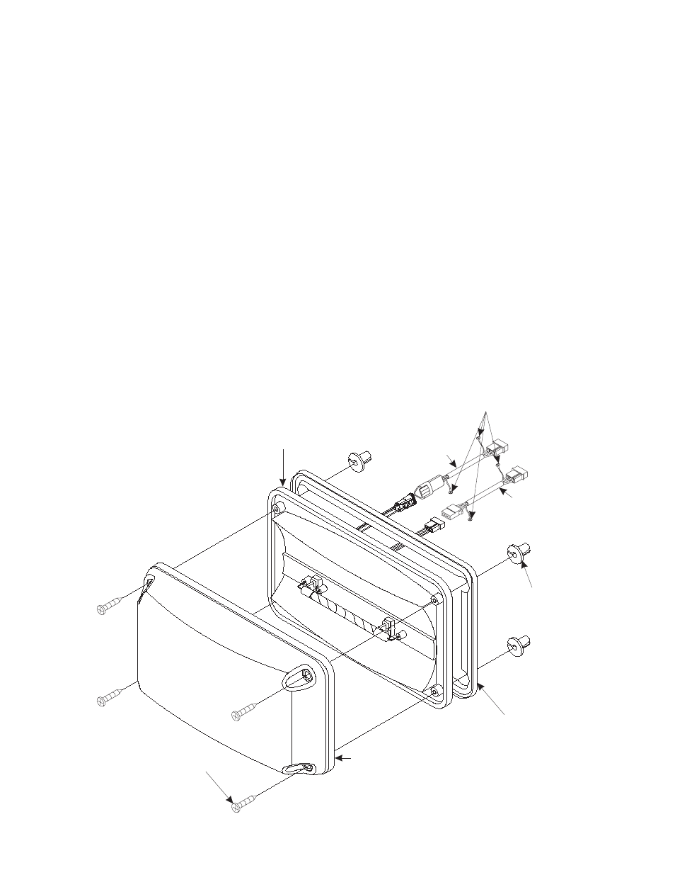
Lens, Amber
Blue
Clear
Green
Red
E-spec Red
Split
68-3183365-10
68-3183365-20
68-3183365-30
68-3183365-40
68-3183365-50
68-3183365E50
02-0383470-**
Mounting Screw
(#8 x 1.5“ PPHSMS)
Reflector
AMP
Deutsch
02-0362189-00
02-0362189-01
Ring Terminals
(to chassis ground)
(AMP)
1 Anode (Red)
2 Cathode (Black)
3 Trigger (White)
(Deutsch)
A Anode (Red)
B Cathode (Black)
C Trigger (White)
Mounting Gasket
(not used with
adhesive-type mounting)
P/N 38-0462719-00
Round Hole
Screw Grommets
P/N 21-1708080603
Cable (AMP - 15’)
P/N 01-0440624-15
Cable (Deutsch - 15’)
P/N 01-0442199-15
3.
Using a .250” drill bit, drill the mounting holes as shown
on the template.
4.
Using a .375” drill bit, drill a wire passage hole where
indicated on the template.
5.
Route the cable assembly through the wiring hole
towards the strobe power supply. Be sure that both ring
terminals are grounded to the vehicle chassis ground.
6.
Plug the 508 into the cable and plug the cable into the
strobe power supply. Test operation of the 508 before
securing it to the vehicle.
7.
Install the round hole grommets into the mounting holes.
Position the lens onto the reflector. Place this assembly
onto the mounting surface and secure using the supplied
mounting screws.
WARNING! To insure proper mounting of this product,
special round hole screw grommets have been included
with your mounting hardware. Do not install this product
without these grommets! Over-tightening the mounting
screws may cause permanent damage to the reflector
and/or lens!
Installation:
There are two ways to mount the 508 lighthead, each offering
its own benefits:
•
Secured to vehicle using supplied #8 x 1½” sheet
metal screws.
•
Secured to vehicle using an industry-strength, double-
sided adhesive tape, like Scotch® brand VHB™ model
4956 foam tape.
This manual will outline the first procedure.
1.
Position the 508 lighthead in its mounting location. Make
sure that the 508 will not interfere with any existing
equipment. Also be aware of any and all items on the
opposite side of the mounting surface to prevent any
possible damage to existing components.
2.
Position the supplied mounting template on the mounting
location and temporarily secure it to the surface. Be sure
the template is FLAT against the surface.
NOTE: Before proceeding, place the reflector against the
template and confirm that the mounting holes on the
template line up with the actual mounting holes on the
reflector.
NOTE: Be sure the drainage provisions for both the
reflector and gasket are on the bottom. Each gasket is
labeled.