Installation, Wiring, Page 2 – Whelen 60A02SAR User Manual
Page 2: 600 series lighthead wiring
Page 2
Installation:
IMPORTANT! It is the responsibility of the installation technician to make sure
that the installation and operation of this product will not interfere with or
compromise the operation or efficiency of any vehicle equipment!
Caution: Permanent mounting of this product will require drilling. It is
absolutely necessary to make sure that no other vehicle components could be
damaged by this process. Check both sides of the mounting surface before
starting. If damage is likely, select a different mounting location.
Hi/Low Intensity (Violet) - This feature allows the user to step the unit down to low
power operation for nighttime use. Apply positive voltage to the VIOLET wire to put
the lighthead into low power. Remove the voltage from the VIOLET wire to restore
normal high power operation.
The table below provides wiring information for the 600 Series lighthead. Refer to the
appropriate Flash Pattern list as determined by the lighthead style:
WARNING! The LED models designated “Steady” must be connected to an
electronic flasher. Allowing the LED to steady burn will damage the lighthead
and void the warranty.
This product draws significantly less current than a
standard incandescent automotive bulb. If your flasher does not operate
properly, it may be necessary to replace your existing flasher module with a
Whelen 3TERM flasher module. Contact your sales representative for specific
vehicle application.
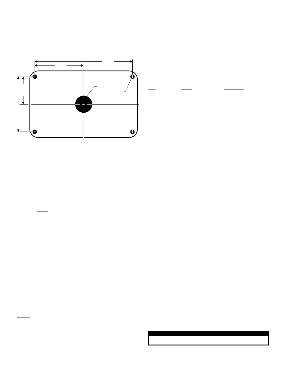
3.250"
1.625"
2.875"
5.750"
1" diameter hole
1/4" diameter
hole (4 places)
CAUTION! DO NOT LOOK DIRECTLY AT THESE LED’S WHILE THEY ARE ON.
MOMENTARY BLINDNESS AND/OR EYE DAMAGE COULD RESULT!
I M P O R TA N T W A R N I N G !
IMPORTANT! Before returning the vehicle to active service, visually
confirm the proper operation of this product, as well as all vehicle
components/equipment.
1. SignalAlert 75 - Alt.
2. SignalAlert 75 - Sim.
3. CometFlash - Alt.
4. CometFlash - Sim.
5. DoubleFlash150 - Alt.
6. DoubleFlash150 - Sim.
7. DoubleFlash75 - Alt.
8. DoubleFlash75 - Sim.
9. SingleFlash375 - Alt.
10. SingleFlash375 - Sim.
11. SingleFlash150 - Alt.
12. SingleFlash150 - Sim.
13. SingleFlash75 - Alt.
14. SingleFlash75 - Sim.
15. ActionFlash - Alt.
16. ActionFlash - Sim.
17. ModuFlash - Alt
18. ModuFlash - Sim.
19. ActionScan - Alt.
20. SSNF
1. SignalAlert™75
2. SignalAlert150
3. SingleFlash 375
4. SingleFlash 150
5. SingleFlash 75
6. DoubleFlash 150
7. DoubleFlash 75
8. CometFlash®75
9. ActionFlash
10. ModuFlash
11. ComAlert
12. ActionScan
13. SignalAlert
14. Steady
Sync-Capable Flash Patterns:
1.
SignalAlert™ 75 - Phase 1
2.
SignalAlert 75 - Phase 2
3.
CometFlash® 75 - Phase 1
4.
CometFlash 75 - Phase 2
5.
DoubleFlash 75 - Phase 1
6.
DoubleFlash 75 - Phase 2
7.
SingleFlash 75 - Phase 1
8.
SingleFlash 75 - Phase 2
9.
ComAlert™ 75 - Phase 1
10. ComAlert 75 - Phase 2
11.
LongBurst™ 75 - Phase 1
12. LongBurst 75 - Phase 2
13. PingPong™ 75 - Phase 1
14. PingPong 75 - Phase 2
Non-Sync Flash Patterns:
15. SingleFlash 60*
16. SingleFlash 90*
17. SingleFlash 120*
18. SingleFlash 300
19. DoubleFlash 150
20. ComAlert 150
21. ActionFlash™ 50
22. ActionFlash 150
23. ModuFlash™
24. ActionScan™
25. Steady
* = California Title XIII compliant
Split Pattern Table:
Standard Pattern Table:
1.
Using the dimensions shown, mark off and drill the four 1/4” diameter mounting
holes and the 1” wire hole into the mounting surface. Check measurements
before drilling.
2.
Install the screw grommet flange into the mounting holes then install a rubber
grommet (customer supplied) into the wire hole.
3.
Using appropriately sized wires (minimum 18 AWG wire), extend the lighthead
wires to their appropriate connections. Fuse the positive connections at 3
Amps and test operation of lighthead before securing it to vehicle.
4.
Position the lighthead onto the mounting surface and secure to the vehicle
using the four #6 x 1-1/2” sheet metal screws.
Wiring:
WARNING!
All customer supplied wires that connect to the positive terminal
of the battery must be sized to supply at least 125% of the maximum operating
current and FUSED at the battery to carry that load. DO NOT USE CIRCUIT
BREAKERS WITH THIS PRODUCT!
The 600 Series lighthead offers the user various features depending on the model.
These features and their usage are as follows:
Scan-Lock™ (White/Violet):
Note that the lighthead must be on to use the ScanLock feature except where
noted.
To advance to the next flash pattern - Apply +12VDC to the WHT/VIO wire for less
than 1 second and release.
To cycle backwards through the flash patterns - Apply +12VDC to the WHT/VIO
wire for more than 1 second and release.
To reset to the factory default flash pattern - Turn off power to the lighthead. While
applying +12VDC to the WHT/VIO wire, turn power to the lighthead on. Continue to
apply voltage to the WHT/VIO wire for 5 seconds. The default pattern will now be
active.
NOTE: A Normally Open momentary switch is suggested to activate the Scan-
Lock™ wire.
SYNC (Grey) - To SYNC two lightheads, configure both lightheads to display the
same Phase 1 pattern. With the power off, connect the Grey wires from each
lighthead. When the lightheads are activated, their patterns will be synchronized. To
configure the two lightheads to alternate their patterns, advance the pattern of either
lighthead to the Phase 2 mode of the current pattern. Remember, Phase 1 patterns
ALWAYS alternate with Phase 2 patterns!
SYNC Pattern Table:
600 Series Lighthead Wiring
Style
Wiring
Pattern Table
Steady (12V)
- LED Color (Power) . . . . . . . N/A (see “WARNING” above)
- BLK (Ground)
Steady (24V)
- LED Color (Power) . . . . . . . N/A (see “WARNING” above)
- BLK/WHT (Ground)
SYNC
- LED Color (Power) . . . . . . . SYNC Pattern Table
- BLK (Ground)
- GRY (SYNC)
- WHT/VIO (Scan-Lock™)
Split
- LED-1 Color (Power) . . . . . Split Pattern Table
- LED-2 Color (Power)
- BLK (Ground)
- WHT/VIO (Scan-Lock)
Hi/Low (12V)
- LED Color (Power) . . . . . . . Standard Pattern Table)
- BLK (Ground)
- VIO (Hi/Low Power)
- WHT/VIO (Scan-Lock)
Hi/Low (24V)
- LED Color (Power) . . . . . . . Standard Pattern Table)
- BLK/WHT (Ground)
- VIO (Hi/Low Power)
- WHT/VIO (Scan-Lock)
- 60A02FAR 60RA6FCR 60BR6FCR 60RC6FCR 60G02FCR 60G02FGR LINZ6A LINZ6A24 LINZ6G IONSMJ IONSMD IONSMM IONSMWJ IONSMWD IONSMWM WIONSMJ WIONSMD WIONSMM WIONSMWJ WIONSMWD WIONSMWM WIONSMCD IONJ IOND IONM IONWJ IONWD IONWM WIONJ WIOND WIONM WIONWJ WIONWD IONA IONWA WIONA WIONWA IONG IONV3A IONV3AW 3SC0CDCR 3SA00FAR 3SBCCDCR 3SRCCDCR 3SR0CDRR IONV1A IONV1AW PAR28DA PAR28DJ UFM8 20C0CDCR 20C0CDCD SFIOND SFIONJ SFIONE SFP1A SFP1G SFP1J SFP1E SFP1D LINZ6K LINZ6J LINZ6D LINZ61 LINZ62 LINZ65 RSA02ZCR RSA03ZCR RVA03ZCR RSC02ZCR RSC03ZCR RVC03ZCR RSG02ZCR RSG03ZCR IONSMA IONSMWA IONSMCA WIONSMA WIONSMWA WIONSMCA MBFX11AA MBFX11JJ VMFX11AA MBFT11AA MBFT11JJ MBCC11JJ MBFF12AA MBFF12JJ VMFF12AA SK02JJ SK02WJJ SK01AA SK01JJ SK01WAA SK01WJJ