Whelen 6SC0ENZR User Manual
Important warning
®
ENGINEERING COMPANY INC.
51 Winthrop Road
Chester, Connecticut 06412-0684
Phone: (860) 526-9504
Fax: (860) 526-4078
Sales Email:[email protected]
Canadian Sales:[email protected]
Customer Service:[email protected]
www.
.com
600 Series Surface Mount LED Scenelight
For warranty information regarding this product, visit
www.whelen.com/warranty
©2010 Whelen Engineering Company Inc.
Form No. 14427A (051211)
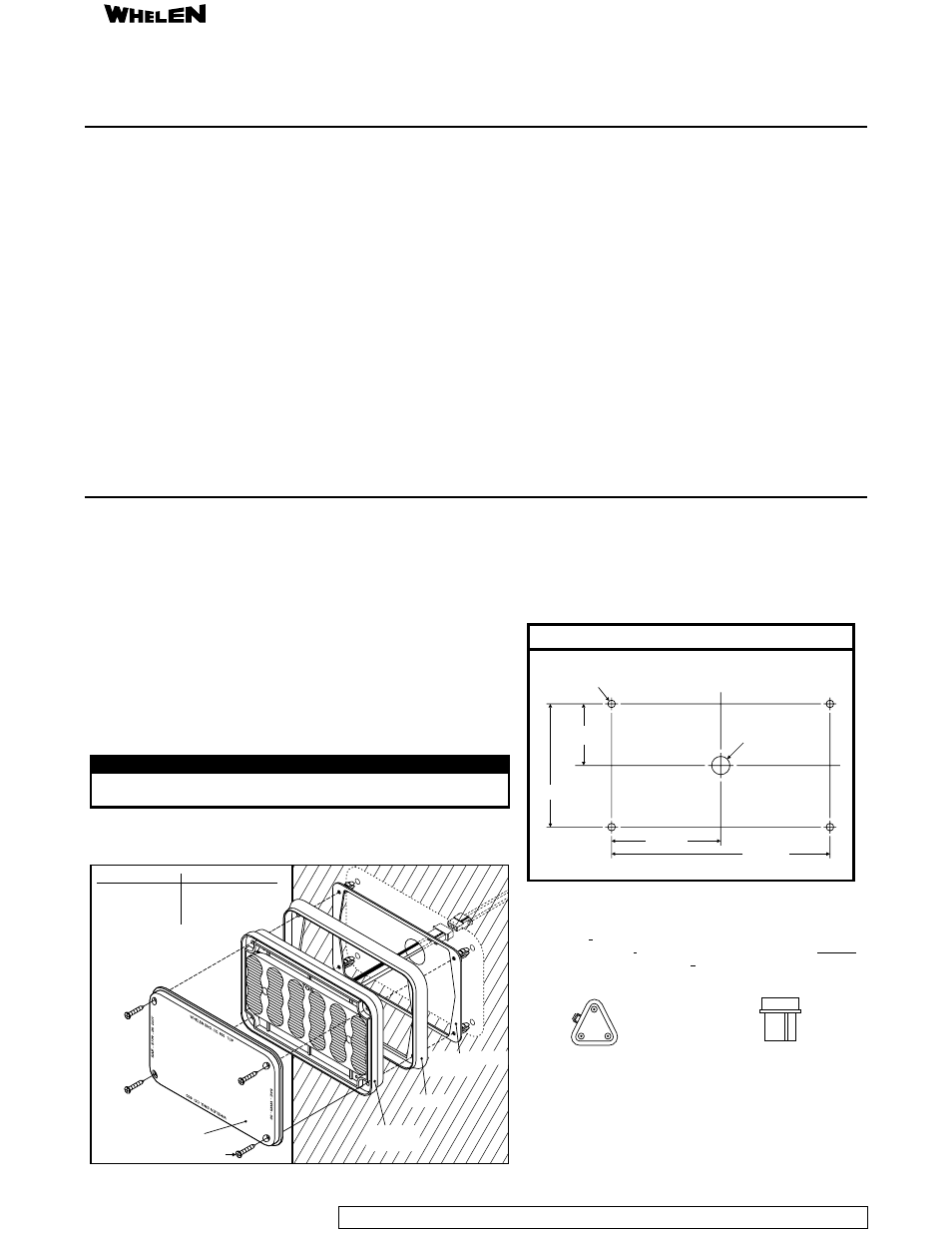
Mounting:
1. Using the mounting diagram shown, mark the locations for the mounting
holes and the wire passage hole. Drill 4 mounting holes with
sing a 1" drill bit .
2. Insert the screw grommet flange into the mounting holes as shown.
3. Using appropriately sized wire, extend the wires through the gasket and
through the wire passage hole. Make the appropriate connections (see table
below for fusing information) and confirm proper operation of the light.
.
.
place the lighthead assembly onto the mounting
surface.
a .250" drill bit.
Drill and de-burr the wire passage hole u
4 Assemble the lens, lighthead and gasket in the order shown While holding all
these components together,
NOTE: Be sure that the lighthead is mounted so that the word
"TOP" is properly positioned as shown.
Safety First
This document provides all the necessary information to allow your Whelen product to be properly and safely installed. Before beginning
the installation and/or operation of your new product, the installation technician and operator must read this manual completely. Important
information is contained herein that could prevent serious injury or damage.
!
!
!
!
!
Proper installation of this product requires the installer to have a
good understanding of automotive electronics, systems and
procedures.
If mounting this product requires drilling holes, the installer MUST
be sure that no vehicle components or other vital parts could be
damaged by the drilling process. Check both sides of the mounting
surface before drilling begins. Also de-burr any holes and remove
any metal shards or remnants.
For this product to operate at optimum efficiency, a good electrical
connection to chassis ground must be made. The recommended
procedure requires the product ground wire to be connected
directly to the NEGATIVE (-) battery post.
If this product uses a remote device to activate or control this
product, make sure that this control is located in an area that
allows both the vehicle and the control to be operated safely in any
driving condition.
Do not attempt to activate or control this device in a hazardous
driving situation.
!
!
!
!
This product contains either strobe light(s), halogen light(s), high-
intensity LEDs or a combination of these lights. Do not look directly
into these lights. Momentary blindness and/or eye damage could
result.
Use only soap and water to clean the outer lens. Use of other
chemicals could result in premature lens cracking (crazing) and
discoloration. Lenses in this condition have significantly reduced
effectiveness and should be replaced immediately. Inspect and
operate this product regularly to confirm its proper operation and
mounting condition. Do not use a pressure washer to clean this
product.
It is recommended that these instructions be stored in a safe place
and referred to when performing maintenance and/or reinstallation
of this product.
FAILURE TO FOLLOW THESE SAFETY PRECAUTIONS AND
INSTRUCTIONS COULD RESULT IN DAMAGE TO THE PRODUCT
OR VEHICLE AND/OR SERIOUS INJURY TO YOU AND YOUR
PASSENGERS!
Pos. -
Pos. -
Pos. -
1 WHITE
2 N/C
3 BLACK
or
BLACK/WHITE
A
(rear)
B
C
Wiring Diagram
3-pos. Socket Conn.
Pos. -
Pos. -
Pos. -
A WHITE
B Sealing Plug
C BLACK
or
BLACK/WHITE
Wiring Diagram
3-pos. Pin Housing
3 2 1
2.875
1.625
MOUNTING DIMENSIONS
.250 Dia.
Mounting Hole (4) Places
3.250
CL
CL
5.750
1" Dia. Wire
Passage Hole
6. Hold the lighthead against the mounting surface and secure the assembly to
the mounting surface using the hardware provided.
IMPORTANT! Before returning the vehicle to active service, visually
confirm the proper operation of this product, as well as all vehicle
components/equipment.
CAUTION! DO NOT LOOK DIRECTLY AT THESE LEDS WHILE THEY ARE ON.
MOMENTARY BLINDNESS AND/OR EYE DAMAGE COULD RESULT!
IMPORTANT WARNING!
WARNING! All customer supplied wires that connect to the
positive (+) terminal of the battery must be sized to supply
at least 125% of the maximum operating current and
“at the battery” to carry that load. DO NOT USE CIRCUIT
BREAKERS WITH THIS PRODUCT!
FUSED
Screw
Lens
Screw Grommet
Flange
Gasket
600 Series
Scenelight
Wire Color
White
Black (12V)
Black/White (24V)
or
Function
(+)VBATT (Fuse@3A)
(-) Ground