Installation, Mounting dimensions, Required mounting depth – Whelen 602000AR User Manual
Page 2
Page 2
A/R
11
0 2 - 0 3 6 3 4 1 6 - ( )
A/R
A/R
A/R
A/R
A/R
3 8 - 0 2 4 2 7 1 7 - 0 0
1
6 8 - 3 1 8 3 5 8 7 E 5 0
10
6 8 - 3 1 8 3 5 8 7 - 5 0
PART NUMBER KEY:
CONNECTOR: 0 =
1 =
AMP CONNECTOR
DEUTSCH CONNECTOR
CONNECTOR:
COLOR:
B =
G =
A =
C =
* =
5 =
BLUE
GREEN
AMBER
CLEAR
SPLIT
KKKE-SPEC RED
R = RED
COLOR:
COLOR:
COLOR:
COLOR:
COLOR:
COLOR:
0 1 - 0 6 6 3 4 1 5 - _ _
CONNECTOR
COLOR
BASIC P/N
6 8 - 3 1 8 3 5 8 7 - 4 0
9
8
6 8 - 3 1 8 3 5 8 7 - 3 0
7
6 8 - 3 1 8 3 5 8 7 - 1 0
5
A/R
4
1 5 - 0 6 1 4 1 6 - 2 8 0
3
4
0 2 - 0 3 6 3 1 7 3 - 0 1
2
A/R
0 2 - 0 3 6 3 1 7 3 - 0 0
1
A/R
6 0 0 S E R I E S L I N E A R S T R O B E / PA R T S L I S T
QTY ITEM
DESCRIPTION
PART NUMBER
0 1 - 0 6 6 3 4 1 5 - ( )
6
6 8 - 3 1 8 3 5 8 7 - 2 0
LENS / SPLIT 600
/
GASKET
LENS MODEL 600 KKKE-SPEC RED
/
/
LENS MODEL 600 RED
/
/
LENS MODEL 600 GREEN
/
/
LENS MODEL 600 CLEAR
/
/
LENS MODEL 600 AMBER
/
/
SCREW #6 X 1-3/4" PPHSMS
/
600 LINEAR STROBE DEUTSCH CONN
/
600 LINEAR STROBE AMP CONN
/
REFLECTOR ASSEMBLY
LENS MODEL 600 BLUE
/
/
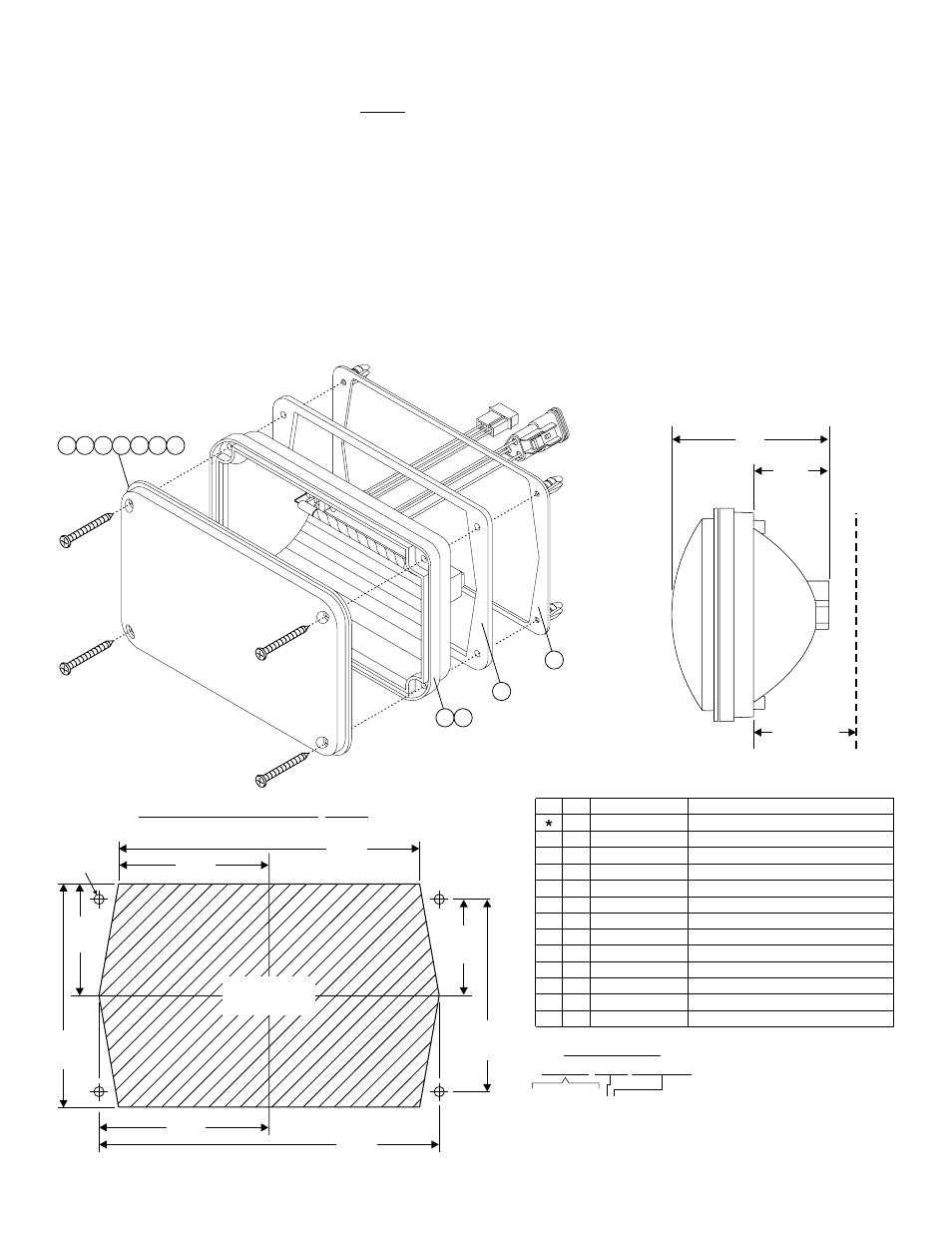
600 Series Linear Strobe Lighthead
MOUNTING DIMENSIONS
3.10"
1.452"
2" MINIMUM
REQUIRED MOUNTING DEPTH
2.545"
5.090"
1.885"
3.770"
1.625"
3.250"
2.875"
5.750"
.250" hole
(4 places)
12 11 - 7 6 D 2 5 8 - 0 0 0
1
SCREW GROMMET FLANGE
AREA TO BE
REMOVED
4 5 6 7 8 9 10
1 2
11
12
Pos. 1 - Annode
Cathode
Trigger
Pos. 2 -
Pos. 3 -
Pos. - Annode
Cathode
Trigger
A
Pos. B -
Pos. C -
Installation:
WARNING! All customer supplied wires that connect to the positive terminal of the battery must be sized to supply at least 125% of
the maximum operating current and FUSED at the battery to carry that load. DO NOT USE CIRCUIT BREAKERS WITH THIS
PRODUCT!
WARNING! The strobe light power supply is a high voltage device. Do not touch or remove the strobe tube assembly while in
operation. Wait 10 minutes after disconnecting the unit from its power source before starting any work or trouble
shooting.
1.
First check behind the proposed mounting area. Note that the mounting surface must be flat. There must be at least 2” clearance behind the
lighthead.
2.
Using the measurements supplied, mark the locations for the mounting holes and lighthead cut-out hole onto the mounting surface. Be sure
to double-check all your measurements before cutting or drilling.
3.
Drill the four .250” mounting holes for the screw grommet flange then cut the lighthead cut-out hole as indicated.
4.
Connect the wires to your Strobe Power Supply (refer to your power supply manual for wiring information. Be sure to test for proper
operation of your lighthead prior to use.