Mounting, Flash pattern synchronization (sync), Specifications – Whelen 70C00VCR User Manual
Page 2: Important warning
Page 2
CAUTION! DO NOT LOOK DIRECTLY AT
THESE LEDS WHILE THEY ARE ON.
MOMENTARY BLINDNESS AND/OR EYE
DAMAGE COULD RESULT!
IMPORTANT WARNING!
IMPORTANT NOTICE!This product has been designed for improved visibility. Prior to installing
this product on any vehicle, check your state motor vehicle codes to confirm that this product
complies with any and all state statutes.
Mounting:
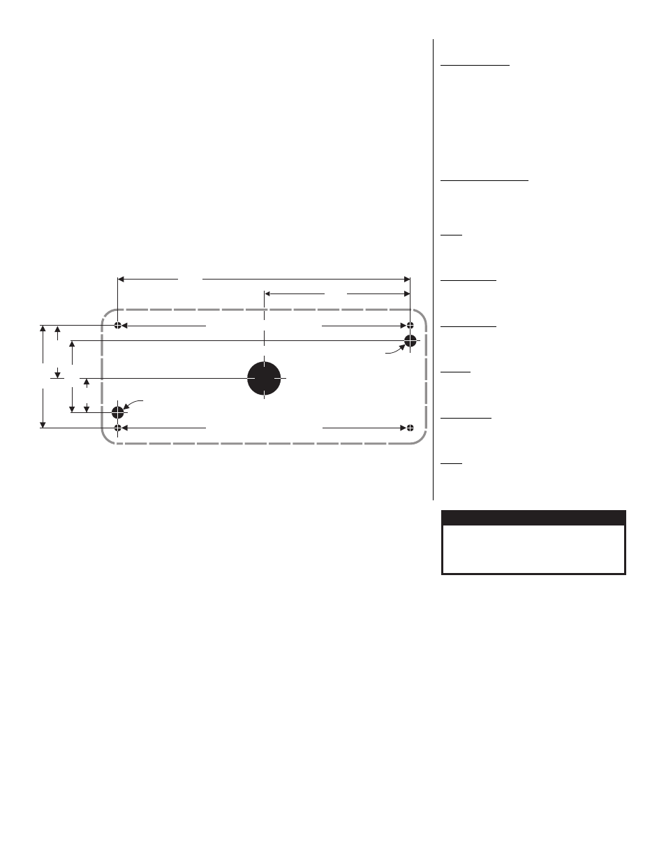
1. Using the dimensions below, mark off and drill the two, 5/16” diameter vent tube holes and the 1”
wire hole into the mounting surface. Make sure lighthead will not interfere with existing equipment
and be aware of any items on the opposite side of the mounting surface.
IMPORTANT WARNING: Always check all measurements before drilling. Measurements are
given in both decimals and fractions for your convenience. For a more accurate measurement
and installation, use the decimals.
2. Insert the two vent tubes extending from the rear of the lighthead into their holes. Using a scribe or
similar tool, mark off the 4 mounting holes.
3. Using a 1/4” drill bit, drill the four mounting holes. Install a grommet (customer supplied) into the 1”
wire hole.
4. Using appropriately sized wires (minimum 18 AWG wire size), extend the lighthead wires to their
connections (see “Wiring Options”). Fuse the +12VDC connections at 3 Amps and test the lighthead
before securing it to the vehicle.
Note:Some 700 series lightheads are equipped with the SYNC feature. These lightheads will
have an extra grey wire (See below).
5. Position the lighthead components onto the mounting surface and secure to the vehicle using the
flange grommet and four supplied #6 x 1-1/4” sheet metal screws.
WARNING!
This product draws significantly less current than a standard incandescent
automotive bulb. If your flasher does not operate properly, it may be necessary to replace your
existing flasher module with a Whelen® 3TERM flasher module. Contact your sales
representative for specific vehicle application.
WARNING! All customer supplied wires that connect to the positive terminal of the battery must
be sized to supply at least 125% of the maximum operating current and FUSED at the battery to
carry the load. DO NOT USE CIRCUIT BREAKERS WITH THIS PRODUCT!
IMPORTANT! Before returning this vehicle to active service, visually confirm the proper operation
of this product, as well as all vehicle components/equipment.
Flash Pattern Synchronization (SYNC):
A SYNC feature is available on selected models. This allows two (or more)
lightheads to flash the same, synchronized pattern in either simultaneous or
alternating mode. In order to enable SYNC mode, it is necessary for the
GREY wires from each lighthead to be connected together.
There is only one pattern available to a SYNC-capable lighthead, offering
both a simultaneous and alternating mode:
SignalAlert™ 75 Simultaneous mode - 75 fpm (Factory Default)
SignalAlert™ 75 Alternating mode - 75 fpm
To help understand how to use SYNC, the principals will be applied to a
sample system consisting of 4 lightheads, with 2 mounted on the rear, driver
side of the vehicle and 2 mounted on the rear, passenger side.
With all the wiring complete, turn on the 4 lightheads. As shipped from the
factory, all the lightheads will be flashing simultaneously.
To configure, for example, the passenger side lightheads to alternate with
the driver side lightheads, change the flash patterns for either the passenger
or driver side lightheads to Alternating.
Important! SYNC-capable LED lightheads can be SYNCed to SYNC-
capable strobe power supplies (such as the CS240S) by wiring their grey
wires together. When connected as such, LED lightheads in their default
pattern (simultaneous) will flash simultaneously with strobe lightheads
connected to the GREEN wire outputs. LED lightheads configured for the
alternating pattern will flash simultaneously with strobe lightheads connected
to the WHITE wire outputs. GREEN wire outputs always alternate with
WHITE wire outputs.
Specifications:
BRAKE/TAIL/TURN
LED Assembly - 120 LEDs (MAX)
Input Voltage
- 12.8 VDC ±20%
Input Current
- Tail - 0.125 Amps
- Brake - 0.70 Amps
Default Pattern - SignalAlert™ Brake
LED Assembly - 56 LEDs (MIN)
Input Voltage
- 12.8 VDC ±20%
Input Current
- Tail - 0.075 Amps
- Brake - 0.375 Amps
Default Pattern - SignalAlert™ Brake
WIDE ANGLE WARNING
Input Voltage
- 12.8 VDC ±20%
Input Current
- 0.40 Amps (Blue / White / Green)
- 0.45 Amps (Amber / Red)
Default Pattern - RapidFire™ 375
TURN
Input Voltage
- 12.8 VDC ±20%
Input Current
- 0.70 Amps
Default Pattern - SignalAlert™ Brake
BACK-UP (12V)
Input Voltage
- 12.8 VDC ±20%
Input Current
- 0.300 Amps
Default Pattern - Steady On
BACK-UP (24V)
Input Voltage
- 25.6 VDC ±20%
Input Current
- 0.150 Amps
Default Pattern - Steady On
ARROW
Input Voltage
- 12.8 VDC ±20%
Input Current
- 0.475 Amps
Default Pattern - Steady
DUAL COLOR
Input Voltage
- 12.8 VDC ±20%
Input Current
- 0.475 Amps
Default Pattern - RapidFire™ 680
SYNC
Input Voltage
- 12.8 VDC ±20%
Input Current
- 0.475 Amps
Default Pattern - SignalAlert™ (Simultaneous)
3.281"
6.562"
5/16"
5/16"
Diameter
Diameter
Vent Hole
Vent Hole
1.187"
1.68"
.84"
2.375"
700 SERIES LED LIGHTHEAD
MOUNTING DIMENSIONS
NOT TO SCALE / FOR MEASUREMENTS ONLY
1/4" Mounting Hole / 4 Places
1/4" Mounting Hole / 4 Places
1"
Wire
Hole