Installation – Whelen 810CA0ZR User Manual
Page 2
Page 2
Installation:
1.
Position the 810 lighthead in its mounting location. Make sure
that the 810 will not interfere with any existing equipment.
Also be aware of any and all items on the opposite side of the
mounting surface to prevent any possible damage to existing
components.
2.
Position the supplied mounting template on the mounting
location and temporarily secure it to the surface. Be sure the
template is FLAT against the surface.
NOTE: Before proceeding, place the reflector against the
template and confirm that the mounting holes on the
template line up with the actual mounting holes on the
reflector.
NOTE: Be sure the drainage provisions for both the reflector
and gasket are on the bottom. Each gasket is labeled.
3.
Using a .250” drill bit, drill the mounting holes as shown on
the template.
4.
The rectangle on the template represents the recommended
location for the wiring hole. Drill a 1” wire access hole
centered as shown on the template. Deburr and install an
appropriately sized grommet in this hole (customer supplied).
5.
Butt splice the 2 RED wires together as shown. Repeat for
the 2 WHITE wires. Connect the RED wire to +12VDC and
the WHITE wire to chassis ground. Fuse the RED wire @ 5
amps.
WARNING! All customer supplied wires that connect to the
positive (+) terminal of the battery, must be sized to supply at
least 125% of the maximum operating current, and fused “at
the battery” to carry that load.
6.
Test operation of the 810 before securing it to the vehicle.
7.
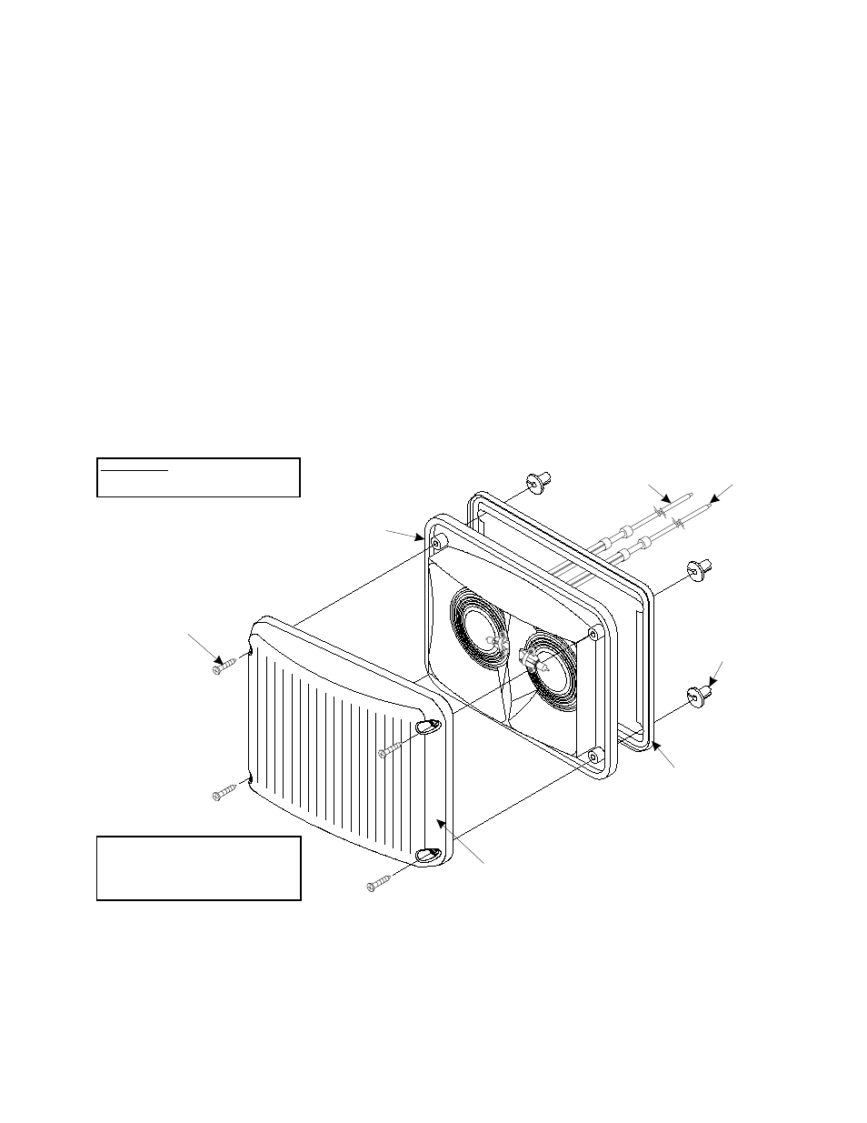
Install the round hole grommets into the mounting holes.
Position the lens onto the reflector. Place this assembly onto
the mounting surface and secure using the supplied
mounting screws.
WARNING! To insure proper mounting of this product,
special round hole screw grommets have been included with
your mounting hardware. Do not install this product without
these grommets! Over-tightening the mounting screws may
cause permanent damage to the reflector and/or lens!
Specifications
INPUT VOLTAGE - 13.5 VDC + 20%
INPUT CURRENT @ 12.8 VDC - 3.9 AMPS
IMPORTANT: Do not install
bulbs exceeding 27 watts.
IMPORTANT:The outer surfaces of this
product may be cleaned with mild soap
and water. Use of any other chemicals
may void product warranty.
Do not use a pressure washer.
Mounting Screw
(#8 x 1 1/2“ P.P.H.S.M.S.)
Mounting Gasket
P/N 38-0483047-00
Reflector
P/N 68-5982436-02
Round Hole
Screw Grommet
P/N 21-1708080603
Lens
(Scenelight / Optic / Clear)
P/N 68-1984058-30
RED
(+12VDC)
WHITE
(GROUND)