Important warning, Installation, Flasher models – Whelen 90AA5SAR User Manual
Page 2: Page 2, Scan-lock™: white-violet wire, Hi/low intensity: violet wire
Page 2
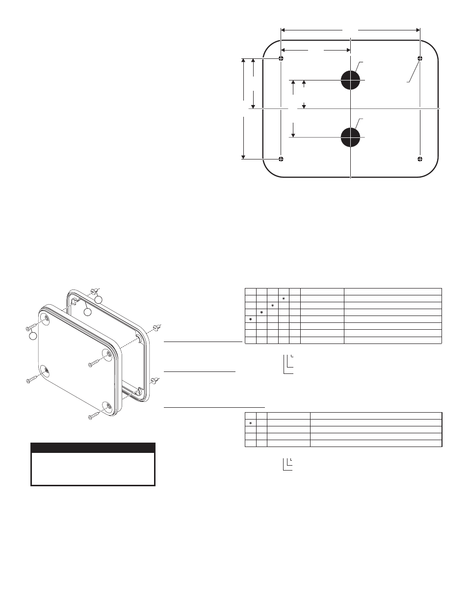
3.62"
7.26"
5.24"
2.62"
3"
1.50"
1" diameter hole
1" diameter hole
1/4" diameter
hole (4 places)
Installation:
WARNING! The LED models designated “external flasher” must be
connected to an electronic flasher. Allowing the LED to steady burn will
damage the lighthead and void the warranty.
External Flasher Models: This product draws significantly less current than a
standard incandescent automotive bulb. If your flasher does not operate
properly, it may be necessary to replace your existing flasher module with a
Whelen 3TERM flasher module. Contact your WHELEN® sales representative
for specific vehicle application.
Note: Make sure lighthead will not interfere with existing equipment or
any items on the opposite side of the mounting surface.
1.
Using the dimensions shown, mark off and drill the four, 1/4” diameter
mounting holes and two, 1” wire holes into the mounting surface. Check
measurements before drilling.
2.
Install the four supplied plastic grommets into the mounting holes then
install rubber grommets (customer supplied) into the wire holes.
3.
Using appropriately sized wires (minimum wire size - 18 AWG), extend
the lighthead wires to their connections. Fuse the positive connections at
3 Amps and test operation of lighthead before securing it to vehicle.
4.
Position the lighthead onto the mounting surface and secure to the
vehicle using the four, #8 x 1-1/2” sheet metal screws.
Flasher Models:
Scan-Lock™: White-Violet Wire /
This feature allows the user to
select from several available flash patterns
TO CYCLE THROUGH ALL PATTERNS: Apply positive voltage to the WHITE-
VIOLET wire for less than 1 second and release to cycle forward. Apply
positive voltage to the WHITE-VIOLET wire for more than 1 second and
release to cycle backward.
TO SET A PATTERN AS DEFAULT: Allow the desired pattern to run for more
than 5 seconds. The lighthead will now display this pattern when active.
TO RESET TO THE FACTORY DEFAULT PATTERN: Turn off power, apply
positive voltage to the WHITE-VIOLET wire, then turn power on.
Available Flash Patterns: SignalAlert™75 / SignalAlert™150 / SingleFlash
375 / SingleFlash 150 / SingleFlash 75 / DoubleFlash 150 / DoubleFlash 75
CometFlash®75 / ActionFlash™ / ModuFlash™ / ComAlert™ / ActionScan™ /
SignalAlert™ Steady / Steady (Brake)
Hi/Low Intensity: Violet Wire /
This feature allows the user to step
the unit down to low power operation for nighttime use.
Apply positive voltage to the VIOLET wire to put the lighthead into low power.
Remove the voltage from the VIOLET wire to restore high power operation.
STYLE/VOLTAGE
1 =
3 =
6 =
8 =
STEADY/24V
LOW POWER/24V
STEADY/12V
LOW POWER 12V
0 1 - 0 6 8 6 4 0 8 8 _ _
0 1 - 0 6 8 6 4 0 8 6 _ _
0 1 - 0 6 8 6 4 0 8 3 _ _
1 5 - 0 8 1 4 1 6 - 2 4 0
0 1 - 0 6 8 6 4 0 8 1 _ _
LENS COLOR
A =
B =
C =
G =
R =
AMBER
BLUE
CLEAR
GREEN
RED
UPPER & LOWER
LED COLORS
K =
E =
D =
J =
P =
M =
AMB/RED
BLU/WHT
WHT/RED
BLU/RED
AMB/GRN
AMB/BLU
A =
B =
AMB/AMB
BLU/BLU
WH /WH
GRN/GRN
RED/RED
AMB/WH
W =
G =
R =
F =
T
T
T
4
4
4
4
900 DUAL LINEAR TIR LOW POWER 12V
900 DUAL LINEAR TIR STEADY 12V
900 DUAL LINEAR TIR LOW POWER 24V
900 DUAL LINEAR TIR STEADY 24V
SCREW, 8 X 1-1/2" PPHSMS SS
2 1 - 1 7 0 8 0 8 0 6 0 3
3 8 - 0 4 8 1 6 9 0 - 0 0
WIRE FUNCTIONS - LO-POWER 12V
LED COLOR -
BLACK -
VIOLET -
WHITE/VIOLET -
P
Ground
Hi/Low Power
Scan-Lock™
ower
1
4
1
1
4
4
1
4
WIRE FUNCTIONS - STEADY 12V
LED COLOR -
BLACK -
ower
P
Ground
WIRE FUNCTIONS - STEADY 24V
LED COLOR -
BLACK/WHITE -
Power
Ground
WIRE FUNCTIONS - LO-POWER 24V
ower
LED COLOR -
BLACK/WHITE -
VIOLET -
WHITE/VIOLET -
P
G
H /L
P
Scan-Lock™
round
i ow ower
SCREW GROMMET, ROUND HOLE
GASKET
SOLID LED COLOR WIRE
Power (Lower Side 1)
BLACK - GROUND
(Lower Side 1)
WHITE/LED COLOR TRACE WIRE
Power (Lower Side 2)
WHITE/BLACK - GROUND
(Lower Side 2)
WHITE/LED COLOR TRACE WIRE
Power (Upper Side 2)
WHITE/BLACK
GROUND (Upper Side 2)
LENS COLOR
A =
B =
C =
R =
AMBER
BLUE
CLEAR
RED
UPPER LED COLOR
A =
B =
D =
J =
K =
M =
R =
AMBER/AMBER
BLUE/BLUE
WHITE/RED
BLUE/RED
AMBER/RED
AMBER/BLUE
RED/RED
PART NUMBER KEY:
LOWER LED COLOR
UPPER LED COLOR
LENS COLOR
0 1 - 0 6 8 6 4 0 9 _ _ _
PART NUMBER KEY:
UPPER & LOWER
LED COLORS
LENS COLOR
STYLE/VOLTAGE
0 1 - 0 6 8 6 4 0 8 _ _ _
LOWER LED COLOR
A =
B =
D =
J =
K =
M =
R =
AMBER/AMBER
BLUE/BLUE
WHITE/RED
BLUE/RED
AMBER/RED
AMBER/BLUE
RED/RED
WIRE FUNCTIONS - EXTERNAL FLASHER 12V
SOLID LED COLOR WIRE
BLACK - GROUND
Power (Upper Side 1)
(Upper Side 1)
ITEM
PART NUMBER
DESCRIPTION
QTY QTY QTY QTY
1
SCREW GROMMET, ROUND HOLE
GASKET
SCREW, 8 X 1-1/2" PPHSMS SS
900 DUAL LINEAR TIR SPLIT
2 1 - 1 7 0 8 0 8 0 6 0 3
3 8 - 0 4 8 1 6 9 0 - 0 0
1 5 - 0 8 1 4 1 6 - 2 4 0
0 1 - 0 6 8 6 4 0 9 _ _ _
4
1
4
ITEM
PART NUMBER
DESCRIPTION
QTY
2
3
1
2
3
3
2
1
CAUTION! DO NOT LOOK DIRECTLY AT
THESE LED’S WHILE THEY ARE ON.
MOMENTARY BLINDNESS AND/OR EYE
DAMAGE COULD RESULT!
IMPORTANT WARNING!