Installation, Wiring & operation, Scan-lock – Whelen VTXFB User Manual
Page 2: Sync
Page 2
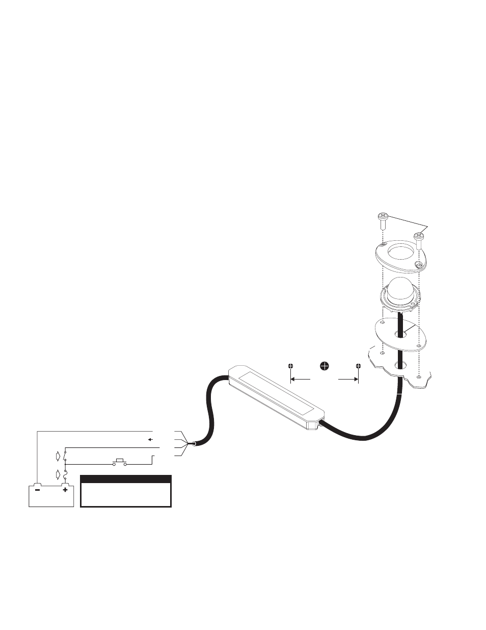
Mounting
Flange
# 4
S h e e t
m e t a l
s c r e w
Lighthead
Gasket
MOUNTING
SURFACE
1.874"
WIRE
HOLE
ONE
INCH
MOUNTING HOLES
3 AMP
Fuse
Connect to other SYNC capable
product or cap off wire.
GREEN
BLACK
RED
WHITE
BATTERY
Normally Open
Momentary Switch
S P S T
Switch
F
SignalAlert™ 75
SignalAlert™ 75
CometFlash® 75
CometFlash® 75
DoubleFlash 75
DoubleFlash 75
PH1
PH2
PH1
PH2
PH1
PH2
PingPong™
SingleFlash 90
SingleFlash 120
SingleFlash 300
DoubleFlash 150
ComAlert™ 150
Non-SYNC Patterns
PH2
14.
15.
16.
17.
18.
19.
Non-SYNC Patterns
Flash Patterns / SYNC
1.
2.
3.
4.
5.
6.
.
8.
9.
10.
11.
12.
13.
7
20.
21.
22.
23.
24.
SingleFlash 75
SingleFlash 75
ComAlert™
ComAlert™
LongBurst™
LongBurst™
PingPong ™
PH1
PH2
PH1
PH2
PH1
PH2
PH1
ActionFlash™ 1
ActionFlash™ 2
ModuFlash™
ActionScan™
Steady
CAUTION! DO NOT LOOK DIRECTLY AT
THESE LEDS WHILE THEY ARE ON.
MOMENTARY BLINDNESS AND/OR EYE
DAMAGE COULD RESULT!
IMPORTANT WARNING!
WARNING: All customer supplied wires that connect to the positive
terminal of the battery must be sized to supply at least 125% of the
maximum operating current and FUSED at the battery to carry that
load. DO NOT USE CIRCUIT BREAKERS WITH THIS PRODUCT!
Permanent mounting of this product will require drilling. It is
absolutely necessary to make sure that no other vehicle components
could be damaged by this process. Check both sides of the
mounting surface before starting. If damage is likely, select a
different mounting location.
IMPORTANT! It is the responsibility of the installation technician to
make sure that the installation and operation of this product will not
interfere with or compromise the operation or efficiency of any
vehicle equipment!
IMPORTANT! Before returning the vehicle to active service, visually
confirm the proper operation of this product, as well as all vehicle
components/equipment.
Installation:
1.
Place the flange onto the mounting surface in its exact mounting
position and mark off the location of the 2 mounting holes and the
center wire hole.
2.
Drill two mounting holes for the two supplied #4 sheet metal screws
(Use a #47 drill bit). Also drill a 1” wire hole in the center of the two
mounting holes.
3.
Insert the lighthead cable and driver module into the wire hole, add
the gasket and secure the light with the sheet metal screws supplied.
4.
Extend the red and black wires to your power source and wire as
shown in the wiring diagram
Wiring & Operation:
This LED lighthead is powered & controlled by a 4-wire cable. All
switches, fuses and fuse blocks are customer supplied.
RED: Positive - Extend RED wire to +12V DC. (Fuse @ 3 amps).
BLACK: Ground - Extend BLACK wire to negative terminal of battery.
GREEN: SYNC - Connect GREEN wire to other SYNC capable lights to
synchronize output. Cap this wire off if it is not used.
WHITE: Scan-Lock™ - Extend WHITE wire to customer
supplied momentary switch (Fuse @ 1 amp).
WARNING: DO NOT ATTEMPT TO USE THIS LIGHTHEAD
WITHOUT THE LED DRIVER MODULE CONNECTED.
Scan-Lock™
In order to program flash patterns, the lighthead must be on. With
the lighthead activated:
TO CHANGE PATTERNS: To advance to the next pattern apply +12VDC
to the WHITE wire for less than 1 second and release. To cycle back to the
previous pattern apply +12VDC to the WHITE wire for more than 1 second
and release.
TO CHANGE THE DEFAULT PATTERN: When the desired pattern is
displayed, allow it to run for more than 5 seconds. The lighthead will now
display this pattern when initially activated.
TO RESTORE THE FACTORY DEFAULT PATTERN: With the light
turned off, apply power to the WHITE wire. With power applied to the
WHITE wire, turn the light on. Allow the unit to run for 3 seconds before
removing power from the WHITE wire.
A normally open momentary switch should be used to control Scan-Lock
operation.
SYNC:
To SYNC two or more lightheads, configure all lightheads to display the
same Phase 1 pattern. Turn the
lightheads off and connect the GREY
wires coming from the lightheads
together. When the lightheads are
activated, the patterns displayed will be
synchronized. To configure specific
lightheads to alternate their patterns with
other lightheads, advance the pattern of
either lighthead to Phase 2 of the current
pattern.
Phase Operation
Phase 1 (PH1) flashes simultaneously
with PH1
Phase 2 (PH2) flashes simultaneously
with PH2
PH1 alternates with PH2