Fig. 3, Cable information, Page 2 1 2 3 – Whelen HA239C User Manual
Page 2
Page 2
1
2
3
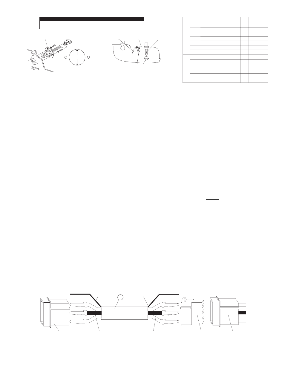
AMP 3-PIN CONNECTOR HOUSING
TO POWER SUPPLY.
SHIELD WIRE (SEE CABLE
INFORMATION).
INSERT WIRES WITH PINS AS
FOLLOWS:
, POSITION 1.
, POSITION 2.
, POSITION 3.
RED WIRE
BLACK WIRE
WHITE WIRE
INSERT WIRES WITH SOCKETS AS
FOLLOWS:
, POSITION 1.
, POSITION 2.
, POSITION 3.
RED WIRE
BLACK WIRE
WHITE WIRE
FIG. 3
1
23
CUT SHIELD WIRE FLUSH
WITH CABLE JACKET.
AMP 3-SOCKET
CONNECTOR
HOUSING.
STROBE LIGHT
HEAD ASSEMBLY.
3-CONDUCTOR POWER
CABLE (OPTIONAL)
2
1
2
3
MOUNTING
HOLE
1.0“ DIA.
0.105“
DIA.
0.105“
DIA.
FIG. 1
Top view of an automotive
“composite” headlight or
taillight housing assembly
Mounted position of
the thermal disc
Focal point of
reflector is the
filament location
of the lamp
Insert the strobe lamp/thermal disc from the back or bottom of the headlight
or rear stoplight housing, as close as possible to the focal point
FIG. 2
Apply a drop of liquid soap to this section to allow for
easier initial installation of the thermal disc, as well as
subsequent installation into the reflector housing.
USE OF THIS PRODUCT WITH A POWER SUPPLY OTHER THAN THOSE
SHOWN ON PAGE 2 COULD CAUSE DAMAGE TO YOUR COMPOSITE HOUSING.
IMPORTANT WARNING!
INSTALLATION OF A STROBE LIGHT INTO A COMPOSITE
AUTOMOTIVE HEADLIGHT OR TAILLIGHT ASSEMBLY:
1.
Select the mounting location for the strobe light head, keeping in
mind the following:
•
The strobe light will share the same reflector as the headlight,
brake light, or signal light. Make sure that the strobe light does
not interfere with the proper operation of these lights (Fig. 2).
•
There must be a minimum of 1” of space between the strobe
light and the lens.
•
The strobe light must not be installed above the horizontal
centerline of the reflector.
•
The strobe light must not be installed above any OEM-supplied
light.
2.
Remove the reflector assembly from the vehicle. Choose a surface in
the rear or bottom of the housing which is as flat as possible. Using a
hole saw, cut a 1” hole (+0.030”/-0.000” tolerance) in the housing as
shown in Fig. 1. Be sure to de-burr this hole completely. Mount the
thermal disc onto the strobe light assembly with the disc holes
aligned with the lamp ears as shown.
3.
Using a twisting motion, insert the lamp/thermal disc assembly into
the reflector housing until it snaps into its proper position. Do not
force the lamp into position. Mark the location for the two mounting
holes (0.105” dia.). Remove the lamp assembly and drill the holes in
this area.
4.
Re-install the lamp ass’y and using the hardware provided, secure
the lamp to the reflector assembly as shown.
WARNING: High Voltage on glass tube. This strobe lamp unit is an
open flash tube with no protective lens. Proper installation is
required. Do not touch the strobe tube assembly while in operation.
IMPORTANT NOTE: If the S30HA_P is being used in an area
previously occupied by an S30HA light assembly, it is important for
the installation technician to seal the mounting holes used by the
previous assembly with RTV or other suitable material!
CABLE INFORMATION
On each end of the optional 3-conductor power cable is a shield wire. Cut
this wire on the end connected to the strobe light head assembly flush with
the cable jacket. The shield wire on the cable end to be connected to the
strobe power supply is to be grounded to the vehicle chassis when the
radio or other communication system interference is a problem. If this
shield wire is not grounded, cut it flush with cable jacket. KEEP THIS
WIRE AS SHORT AS POSSIBLE WHEN GROUNDING.
NOTE: For radio frequency interference protection, it is advisable to
ground the shield wire on the power supply end.
NOTE: Whelen strobe light systems are designed to interface with
the Whelen UPS strobe light power supply. Detailed wiring, switching
and installation instructions are enclosed with the UPS unit.
WARNING: When connecting the AMP connector housing to the AMP
pins and sockets located on the 3-conductor cable, OBSERVE THE
COLOR OF THE WIRES TO BE CONNECTED TO PIN NUMBER
POSITIONS as indicated in Fig. 3.
WARNING: The Strobe Light Power Supply is a high voltage device.
Do not remove strobe tubes or dismantle strobe light head assembly
while in operation. WAIT 10 MINUTES after turning off power before
starting work or any trouble shooting.
WARNING! All customer supplied wires that connect to the positive
terminal of the battery must be sized to supply at least 125% of the
maximum operating current and FUSED at the battery to carry that
load. DO NOT USE CIRCUIT BREAKERS WITH THIS PRODUCT!
WARNING! Automotive composite housings use low-temp plastic in
their construction. The use of strobe power supplies in excess of 10
watts per outlet, may cause the housings to melt. Use the supplied
thermal disc around each HA239 as shown to conduct the heat away
from the vehicle reflector housing.
* When using the HA239 with the SPS660, it is important to follow
these connectivity guidelines:
•
When using only 2 strobe lights, ONLY USE outlets 1 & 2!
•
When using only 4 strobe lights, ONLY USE outlets 3, 4, 5 & 6!
Modification of your vehicle’s reflector housings may void your
vehicle warranty. Check with dealer/supplier before installation.
1.
1
S30HARP FLASH TUBE ASSEMBLY, RED
36-0363017-R0
36-0363017-C0
36-0363017-B0
36-0363017-A0
36-0363017-V0
36-0363017-G0
07-742741-000
1
S30HAAP FLASH TUBE ASSEMBLY, AMBER
S30HABP FLASH TUBE ASSEMBLY, BLUE
S30HACP FLASH TUBE ASSEMBLY, CLEAR
1
1
S30HAGP FLASH TUBE ASSEMBLY, GREEN
THERMAL DISC
S30HAVP FLASH TUBE ASSEMBLY, VIOLET
1
1
1
-
5 FT. EXTENSION CABLE
01-0440624-05
2.
-
10 FT.EXTENSION CABLE
01-0440624-10
-
15 FT.EXTENSION CABLE
01-0440624-15
-
20 FT.EXTENSION CABLE
01-0440624-20
-
25 FT.EXTENSION CABLE
01-0440624-25
-
30 FT.EXTENSION CABLE
01-0440624-30
ITEM
MODEL AND DESCRIPTION
QTY.
PART NO.